Ford Duraspark II & TFI Ignition System Wiring Diagrams - EEC-IV PIP/SPOUT
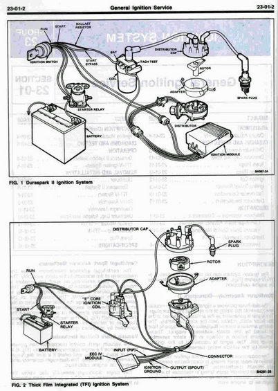
Ford general ignition service wiring diagrams for the Duraspark II and Thick Film Integrated (TFI) ignition systems.
This page (23-01-2, "General Ignition Service") from a Ford service manual presents two labeled ignition system diagrams. Figure 1 illustrates the Duraspark II ignition system, identifying the ignition switch (with RUN, START, START BYPASS circuits), ballast resistor, coil with BAT and TACH TEST terminals, distributor cap, rotor, adapter, spark plug, starter relay, battery, distributor, and ignition module (drawing B4097-2A). Figure 2 illustrates the Thick Film Integrated (TFI) ignition system, showing the distributor cap, rotor, adapter, spark plug, RUN and START circuits, the "E" core ignition coil, starter relay, battery, EEC-IV module with INPUT (PIP) and OUTPUT (SPOUT) signal connections, a connector, and ignition ground (drawing B4281-2B). A reader can learn the overall component layout and wiring relationships of both Ford ignition system types: the older Duraspark II system with its ballast resistor and separate ignition module, and the newer computer-controlled TFI system in which the EEC-IV module receives the PIP (Profile Ignition Pickup) signal and outputs the SPOUT (Spark Output) signal. Mirrored bleed-through from the reverse page (a section index for Section 23-01) is visible but not readable in detail.
Is this accurate? Sign in to help verify it.
Frequently asked questions
- What ignition systems are shown in this diagram?
- Two systems: Figure 1 shows the Duraspark II ignition system, and Figure 2 shows the Thick Film Integrated (TFI) ignition system.
- What components make up the Duraspark II ignition system?
- The ignition switch (RUN, START, and START BYPASS circuits), ballast resistor, coil with BAT and TACH TEST terminals, distributor cap, rotor, adapter, spark plug, starter relay, battery, distributor, and ignition module.
- What signals connect the TFI system to the EEC-IV module?
- The diagram shows an INPUT (PIP) signal into the EEC-IV module and an OUTPUT (SPOUT) signal from the module, along with a connector and ignition ground.
- Does the TFI system use a ballast resistor like Duraspark II?
- No ballast resistor is shown in the TFI diagram; it uses an "E" core ignition coil with RUN and START feeds, whereas the Duraspark II diagram shows a ballast resistor.
- What kind of coil does the TFI system use?
- An "E" core ignition coil, as labeled in Figure 2.
Comments
More from this build













No comments yet.