Ford Bronco Track Bar / Axle Bracket Dimensions - AutoCAD Blueprint Template
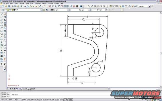
CAD dimensioned drawing of a bracket part with two holes and overall measurements shown in AutoCAD.
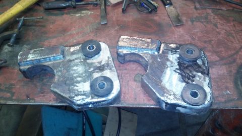
This document is a screenshot of AutoCAD 2007 displaying a fully dimensioned 2D drawing from a file named "Wheel offset.dwg." The drawing shows a flat, roughly C-shaped bracket or plate with a deep U-shaped cutout on its left side and two round holes, each dimensioned at Ø1 1/4". Key dimensions include an overall width of 5 3/4" across the top, an overall height of 7 7/16", 4 9/16" from the left edge to the upper hole center, 4 1/16" from the left edge to the lower hole center, an upper-left tab height of 1 3/4", the upper hole located 1 1/8" from the top edge, the lower hole located 1 3/16" from the bottom edge, and a 13/16" step at the lower-left of the part. A reader can use these dimensions to fabricate the bracket from plate stock. Given the uploader's album context (axle, track bar, and suspension references for a 1995 Ford Bronco) and the filename "wmra-c-dims," this appears to be a template for a suspension/axle bracket, though the document itself carries no vehicle, year, or part-number identification. The AutoCAD command line shows a recent _qsave operation.
Is this accurate? Sign in to help verify it.
Frequently asked questions
- What size are the two holes in this bracket drawing?
- Both round holes are dimensioned at Ø1 1/4" (1.25 inch diameter).
- What are the overall dimensions of the bracket?
- The bracket is 5 3/4" wide across the top and 7 7/16" tall overall.
- Where are the hole centers located?
- The upper hole center is 4 9/16" from the left edge and 1 1/8" down from the top edge. The lower hole center is 4 1/16" from the left edge and 1 3/16" up from the bottom edge.
- What software was used to create this drawing?
- AutoCAD 2007; the file is named "Wheel offset.dwg" per the title bar.
- Does the drawing specify material thickness?
- No. The drawing is a 2D profile with hole and edge dimensions only; no thickness, material, or part number is shown.
Comments
More from this build







No comments yet.