Ford Rear Axle Assembly Exploded View - Trac-Lok, Full Float & Semi-Float

Reference · 1992-1996 BroncoAll 169 exploded parts diagrams
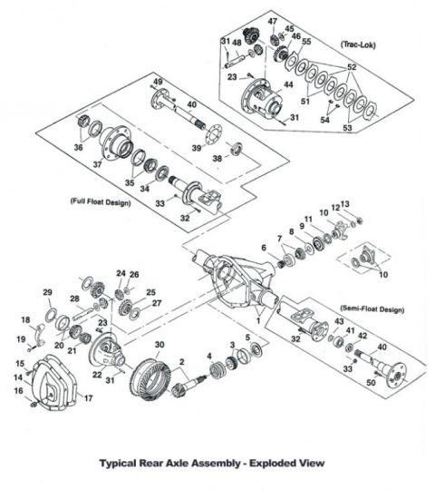
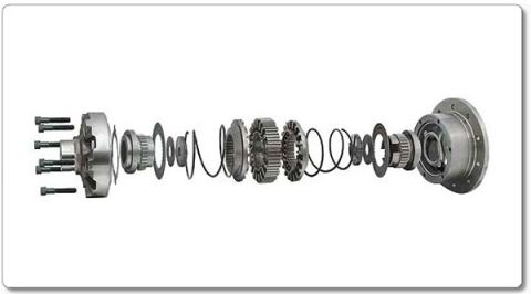
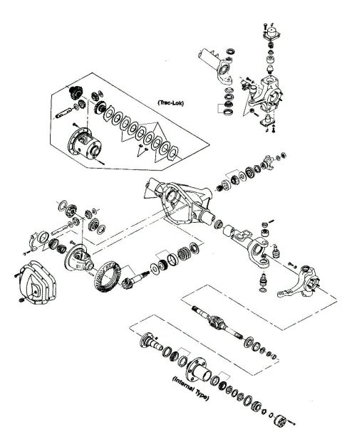
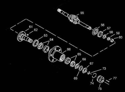
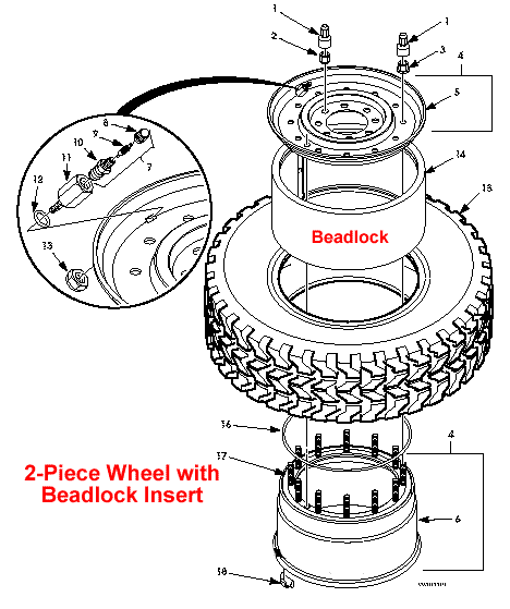









Exploded parts breakdown of a typical rear axle assembly showing full-float and semi-float designs with numbered bearings, gears and shafts.
Part of 1992-1996 Ford Bronco Exploded Parts Diagrams
This document is an exploded-view illustration of a typical rear axle assembly, showing three distinct configurations in one drawing: a Trac-Lok (limited-slip) differential case assembly, a Full Float Design axle shaft/hub arrangement, and a Semi-Float Design axle shaft arrangement. Components are identified only by numbered callouts (ranging from 1 through 55); no legend or parts table is included in the image, so part names and part numbers must be obtained from an accompanying key. The main portion of the drawing shows the axle housing (item 1) with the differential carrier components exploded to the lower left, including the ring gear (30), pinion gear (2), bearings, shims, seals, and the differential cover with bolts (16, 17). The upper-left inset details the Full Float Design with its hub, bearings, seals, axle shaft (40), and axle flange hardware. The upper-right inset shows the Trac-Lok differential internals, including clutch pack components (51, 52, 53), side gears, and pinion gears. The lower-right inset shows the Semi-Float Design axle shaft, bearing, retainer, and flange components. This diagram is useful for identifying the relative position and assembly order of rear axle components when disassembling or rebuilding a rear differential, though specific part identification requires the matching numbered parts list.
Is this accurate? Sign in to help verify it.
Frequently asked questions
- What axle designs are shown in this exploded view?
- The diagram shows three configurations: a Trac-Lok differential assembly, a Full Float Design axle, and a Semi-Float Design axle, all labeled within the drawing.
- Does this diagram include a parts legend or part names?
- No. Components are identified only by callout numbers (1 through 55); no legend, part names, or part numbers appear in the image.
- What is the difference between the Full Float and Semi-Float sections in the diagram?
- They are shown as separate exploded insets: the Full Float Design inset (items such as 32-40, 49) shows a hub and bearing arrangement on the axle tube, while the Semi-Float Design inset (items such as 41-43, 50, 32, 33) shows the axle shaft with its own bearing and flange.
- Which callout numbers relate to the Trac-Lok differential?
- The Trac-Lok inset includes callouts 23, 31, 44, 45, 46, 47, 48, 51, 52, 53, 54, and 55, showing the differential case and its internal clutch and gear components.






No comments yet.