1994-95 Mustang 5.0L EEC-IV CCRM Wiring Diagram & Pinout - Ford
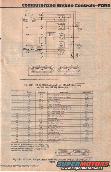
EEC-IV CCRM wiring diagram (Fig 120) and 50-pin connector pin-usage table (Fig 121) for the 1994-95 Mustang 5.0L/V8-302 MA SFI engine, listing circuit, wire color and application per pin.
This scanned page from a Ford computerized engine controls reference manual (page 8-73, Electronic Engine Control System IV / EEC-IV section) documents the Constant Control Relay Module (CCRM) for the 1994-95 Ford Mustang with the 5.0L V8-302 MA SFI engine. Fig. 120 is a wiring schematic showing the EEC-IV CCRM circuit, including the battery, ignition switch, EEC power relay, fuel pump relay, inertia fuel shutoff switch, fuel pump, voltage inverter, low fan control (LFC) relay, high fan control (HFC) relay, A/C WAC relay, cooling fan motor, A/C clutch coil, A/C demand switch, and cyclic pressure switch. Pinout views of both the CCRM harness connector and CCRM module connector are shown. Fig. 121 provides a 24-pin CCRM pin-usage table listing each pin's circuit number, wire color, application, and abbreviation (e.g., pin 5, circuit 238, DG/Y, Power to Fuel Pump, PTP; pin 12, circuit 361, R, Vehicle Power, VPWR). A caution note warns that probing the 60-pin EEC connector with a DVOM probe will permanently damage the pin connectors and directs use of a breakout box. Reference IDs FM0159400865000X and FM0159400866000X appear on the figures.
This document covers 1994-1995, which may differ from this 1995 Ford Bronco.
Is this accurate? Sign in to help verify it.
Frequently asked questions
- What wire color and circuit number is the fuel pump power output on the 1994-95 Mustang 5.0L CCRM?
- Pin 5, circuit 238, dark green/yellow (DG/Y), labeled Power to Fuel Pump (PTP).
- Which CCRM pins control the cooling fan speeds?
- Pins 1 and 2 (circuit 260, R/O) are Power to Cooling Fan Low Speed; pins 6 and 7 (circuit 261, O/BK) are Power to Cooling Fan High Speed. Pin 14 (circuit 228, DB) is Low Speed Fan Control (LFC) and pin 17 (circuit 639, LG/P) is High Speed Fan Control (HFC).
- Which pins provide vehicle power (VPWR) from the CCRM?
- Pins 12 and 24, both circuit 361 with red (R) wires, are Vehicle Power (VPWR).
- Can I probe the 60-pin EEC connector directly with a DVOM?
- No. The document warns that probing the 60-pin connector with a DVOM probe will result in permanent damage to the pin connectors; always probe as directed using the breakout box.
- What relays are contained in the CCRM circuit shown?
- The schematic shows the EEC power relay, fuel pump relay, LFC (low fan control) relay, HFC (high fan control) relay, and the solid-state A/C WAC relay, along with a voltage inverter.
Comments
More from this build







No comments yet.