1984-96 Ford EFI Sensor Values Chart - MAF, ECT, TR, DPFE & Solenoid Ohm Specs
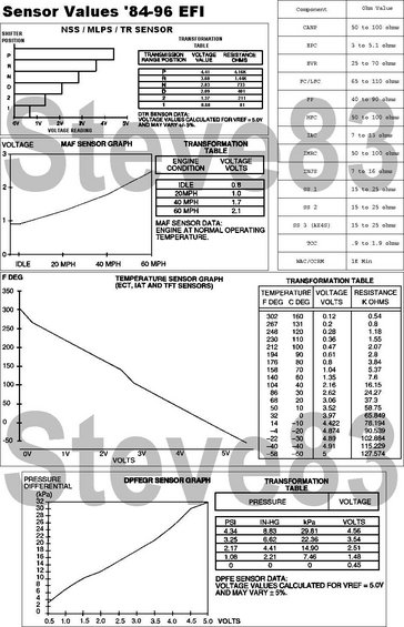
Reference chart of 1984-96 EFI sensor values listing MAF, temperature and pressure sensor voltages, resistances and graphs.
Part of 1987-1991 Ford Bronco Data & Spec Plates
This reference sheet, titled "Sensor Values '84-96 EFI," compiles diagnostic sensor specifications for Ford EFI systems from 1984 through 1996. It includes four graph/table pairs: (1) the NSS/MLPS/TR (transmission range) sensor, showing expected voltage and resistance for each shifter position (P through 1, e.g., P = 4.41V / 4.16K ohms), calculated for VREF = 5.0V ±5%; (2) the MAF sensor, giving voltage values at idle (0.8V) and at 20, 40, and 60 MPH (1.0, 1.7, 2.1V) with the engine at normal operating temperature; (3) the temperature sensors (ECT, IAT, and TFT), giving voltage and resistance values across a range from 302°F/160°C (0.12V, 0.54K ohms) down to -58°F/-50°C (5V, 127.574K ohms); and (4) the DPFE/EGR pressure sensor, correlating pressure differential (PSI, IN-HG, kPa) with output voltage. A side table lists resistance specifications for solenoids and actuators including CANP, EPC, EVR, FC/LFC, FP, HFC, IAC, IMRC, injectors (INJS 7-16 ohms), shift solenoids SS1/SS2/SS3 (AX4S), TCC, and WAC/CCRM. Useful for testing sensors and solenoids with a multimeter on 1984-1996 Ford EFI vehicles.
Is this accurate? Sign in to help verify it.
Frequently asked questions
- What voltage should a Ford MAF sensor read at idle?
- Per the MAF sensor transformation table, at idle (engine at normal operating temperature) the MAF should read 0.8 volts; 20 MPH = 1.0V, 40 MPH = 1.7V, 60 MPH = 2.1V.
- What is the correct resistance for Ford EFI fuel injectors?
- The component resistance table lists INJS (injectors) at 7 to 16 ohms.
- What are the TR/MLPS sensor voltage values for each gear position?
- P = 4.41V (4.16K ohms), R = 3.60V (1.44K), N = 2.83V (733), D = 2.09V (401), 2 = 1.37V (211), 1 = 0.68V (81). Values are calculated for VREF = 5.0V and may vary +/- 5%.
- What should the ECT or IAT sensor read at normal operating temperature (around 194°F)?
- At 194°F (90°C) the temperature sensor should read 0.61 volts with a resistance of 2.8K ohms.
- What resistance should the IAC valve measure?
- The chart lists IAC resistance as 7 to 13 ohms.
Comments
More from this build














No comments yet.