1995 MLP/TR sensor connector swap wire splice soldering steps 1-…
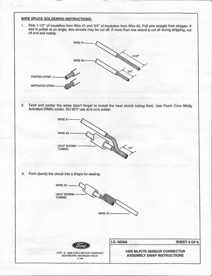
Ford I.S. 6628A sheet 5 of 6: strip 1-1/2" and 3/4" of insulation, twist and solder with RMA solder, then form the splice for sealing.
Part of 1987-1991 Ford Bronco Service Procedures
WIRE SPLICE SOLDEHING INSTRUCTIONS: o 1. Strip 1-1/ of insulation from Wire #1 and 31 of insulation from Wire #2. Pull wire straight from stripper. If wire is pulled at an angle, wire strands mayr be cutoff. if more than one strand is cut Off during stripping, cut Off end and restrip. WIRE #1 . 11112 WIRE #2 a 45%/ , 2. Twist and solder the wires (dont forget to install the heat shrink tubing first). Use Rosin Core Mildly Activated (RMA) solder. DO NOT use acid core solder. PROPER STRIP IMPROPER STRIP WIRE #1 WIRE #2 ' HEAT SHRINK TUBING 3. Form (bend) the circuit into a shape for sealing. WIRE #2 HEAT SHRINK TUBING WIRE #1 LS. 6628A SHEET 5 0F 6 ~ 1 1995 MLPrrR SENSOR CONNECTOR cpoggggfimii 3313? ASSEMBLY SWAP INSTRUCTIONS 11-96
Is this accurate? Sign in to help verify it.
Comments
More from this build














No comments yet.