1995 Ford MLP/TR Sensor Connector Swap - Wire Crimp Splice Instructions (Pg 4)
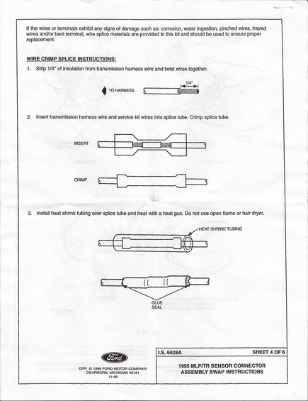
Sheet 4 of the Ford 1995 MLP/TR connector swap (I.S. 6628A); wire crimp-splice procedure: strip 1/4 inch, twist, crimp splice tube, then apply heat-shrink glue-seal tubing.
Part of 1987-1991 Ford Bronco Service Procedures
This document is sheet 4 of 6 from Ford instruction sheet I.S. 6628A, titled "1995 MLP/TR Sensor Connector Assembly Swap Instructions," copyright 1996 Ford Motor Company, Dearborn, Michigan (dated 11-96). The page covers wire crimp splice procedures to be used when replacing damaged wiring during the MLP/TR (Manual Lever Position / Transmission Range) sensor connector swap. It begins by advising that if wires or terminals show damage such as corrosion, water ingestion, pinched wires, frayed wires, or bent terminals, the splice materials provided in the kit should be used. The three-step splice procedure instructs the technician to: (1) strip 1/4 inch of insulation from the transmission harness wire and twist the wires together; (2) insert the transmission harness wire and service kit wires into the splice tube and crimp it; and (3) install heat shrink tubing over the splice tube and shrink it with a heat gun, explicitly warning not to use an open flame or hair dryer. Illustrations show the stripped wire, the insert and crimp steps, the heat shrink tubing placement, and the glue seal that forms at both ends of the shrunk tubing.
Is this accurate? Sign in to help verify it.
Frequently asked questions
- How much insulation should be stripped from the transmission harness wire before splicing?
- Strip 1/4 inch of insulation from the transmission harness wire and twist the wires together.
- What tool should be used to shrink the heat shrink tubing over the splice?
- Use a heat gun. The instructions specifically say do not use an open flame or hair dryer.
- When should the wire splice materials in the kit be used?
- If the wires or terminals exhibit any signs of damage such as corrosion, water ingestion, pinched wires, frayed wires and/or a bent terminal, the splice materials provided in the kit should be used to ensure proper replacement.
- What Ford instruction sheet is this page from?
- It is Sheet 4 of 6 of Ford I.S. 6628A, "1995 MLP/TR Sensor Connector Assembly Swap Instructions," copyright 1996 Ford Motor Company, dated 11-96.
- What are the three steps of the wire crimp splice procedure?
- 1) Strip 1/4" of insulation from the transmission harness wire and twist wires together; 2) Insert the harness wire and service kit wires into the splice tube and crimp it; 3) Install heat shrink tubing over the splice tube and heat it with a heat gun (a glue seal forms at the ends).
Comments
More from this build














No comments yet.