SuperMotors SuperMotors SUPERMOTORS Search: try “orange Bronco on 35s”
Home/ Registry/ Ford/ Bronco/ 1987-1991/ “Eddie Bauer”/ Photo supermotors.net/registry/media/858501

Ford I.S. 6628A sheet 2 of 6, 1995 MLP/TR sensor connector assem…
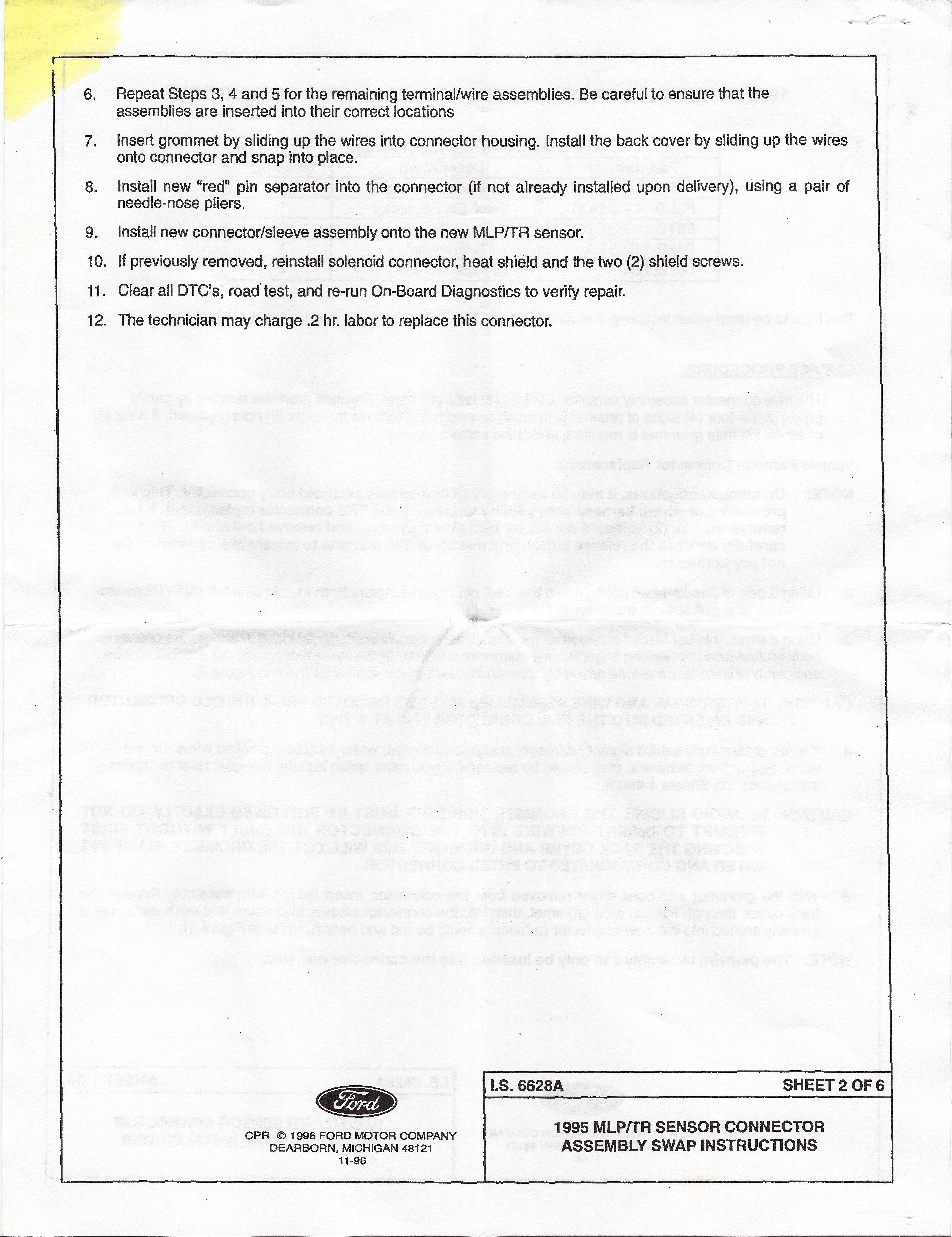
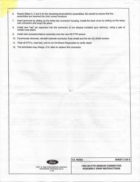
Ford I.S. 6628A sheet 2 of 6, 1995 MLP/TR sensor connector assembly swap steps 6 through 12
Ford I.S. 6628A sheet 2 of 6, 1995 MLP/TR sensor connector assembly swap steps 6 through 12Original file
Ford I.S. 6628A sheet 2 of 6, 1995 MLP/TR sensor connector assembly swap steps 6 through 12

Reference · 1987-1991 BroncoAll 95 service procedures
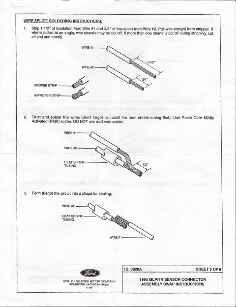
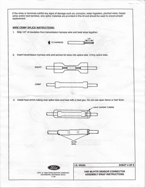
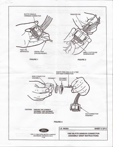
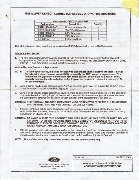
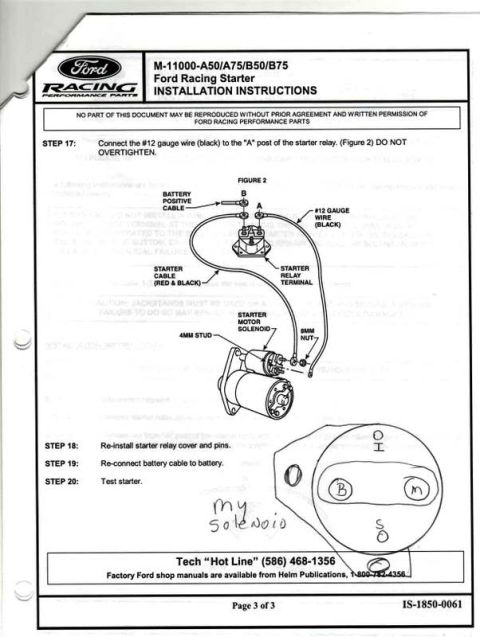
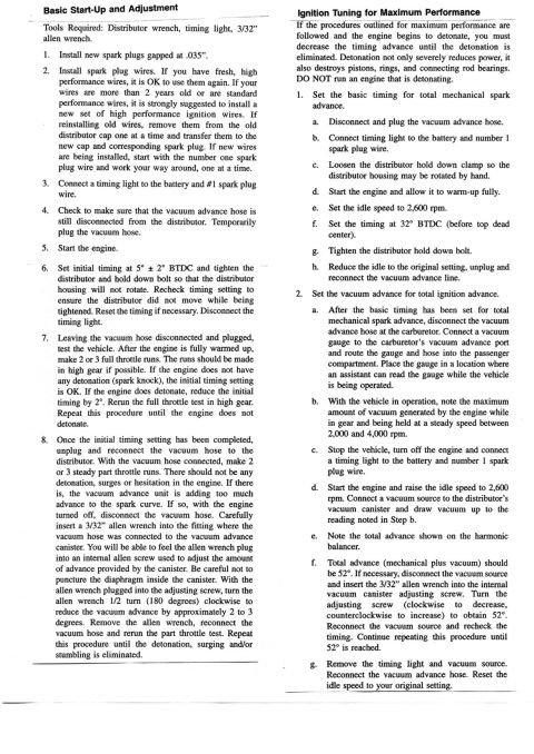
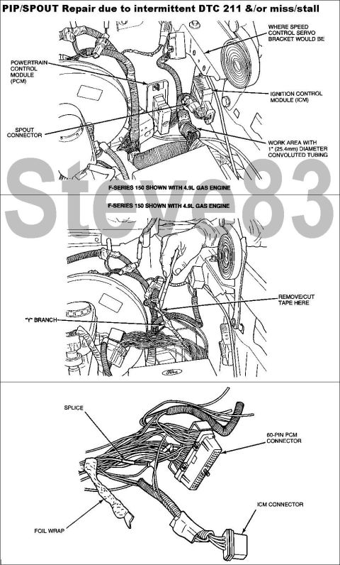
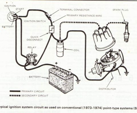
1995 MLP/TR sensor connector swap wire splice soldering steps 1-3 with strip lengths and heat shrink 1995 Ford MLP/TR Sensor Connector Swap - Wire Crimp Splice Instructions (Pg 4) 1995 Ford MLP/TR Sensor Connector Swap Instructions - I.S. 6628A Sheet 3 of 6 Ford I.S. 6628A sheet 2 of 6, 1995 MLP/TR sensor connector assembly swap steps 6 through 12 1995 Ford MLP/TR Sensor Connector Swap Instructions - E4OD Kit F5TZ-7A247-AVMR Ford Racing M-11000-A50/A75/B50/B75 starter wiring, Figure 2, with hand-drawn solenoid terminal sketch Vacuum Advance Distributor Tune-Up & Timing Adjustment Procedure - Ford Bronco Ford PIP/SPOUT Wiring Repair for DTC 211 Miss/Stall - F-150 4.9L Diagrams 95service procedures1987-1991 Ford Bronco More reference 1973-1974 Ford Point-Type Ignition System Circuit Diagram - Coil & DistributorWiring diagram Ford Thermactor Air Bypass Valve Cutaway Diagram - Port IdentificationSchematic Ford 5.8L important engine information decal with 10° BTDC timing check and ASF-32C plugSpec plate Ford 5.0L V8 PCV Valve & Hose Routing Diagram - 9A474, 6B890, 6A664Exploded parts Ford 5.0L/5.8L Air Throttle Body Assembly Diagram - Canister Purge Ports & TPSManual page 1990 Bronco Major Standard Equipment sheet with interior features and functional specs by trimBrochure Borgeson Steering Intermediate Shaft Measurement Diagram - U-Joint Length B & CBlueprint Ford Thermactor Combination Valve Diagram - Air Bypass/Control Ports LabeledVacuum routing 1990 Ford Bronco Fuse Panel Diagram: Fuse Positions, Amps & Circuits (11-2)Fuse chart Ford V8 Intake Manifold Bolt Tightening Sequence Diagram - Stud LocationsTorque spec

Ford instruction sheet I.S. 6628A, sheet 2 of 6: steps 6-12 for swapping the 1995 MLP/TR sensor connector, including red pin separator and .2 hr labor.

Part of 1987-1991 Ford Bronco Service Procedures

AI caption · Photo 614 of 1787

6. Repeat Steps 3, 4 and 5 for the remaining terminal/wire assemblies. Be careful to ensure that the assemblies are inserted into their correct locations 7. insert grommet by sliding up the wires into connector housing. Install the back cover by sliding up the wires onto connector and snap into place. 8. install new red pin separator into the connector (if not already installed upon delivery), Using a pair of needle-nose pliers. 9. Install new connector/sleeve assembly onto the new MLP/TR sensor. 10. If previously removed, reinstall solenoid connector, heat shield and the two (2) shieid screws. 11. Clear all DTCs, road test, and re-run On-Board Diagnostics to verify repair. 12. The technician may charge .2 hr. labor to replace this connector. , LS. 6628A SHEET 2 OF 6 CPR 1996 soap MOTOR COMPANY 1 995 MLPITR SENSOR CONNECTOR DEARBORN, MlCHIGAN 43121 ASSEMBLY SWAP INSTRUCTIONS 11-96

Is this accurate? Sign in to help verify it.

Comments

No comments yet.

More 1987-1991 Broncos