Ford TFI E-Core Ignition Coil Test Light Diagnosis - Coil Negative TACH Lead
Reference · 1987-1991 BroncoAll 95 service procedures
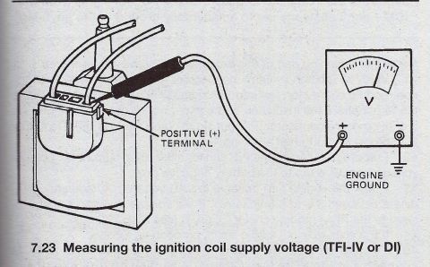
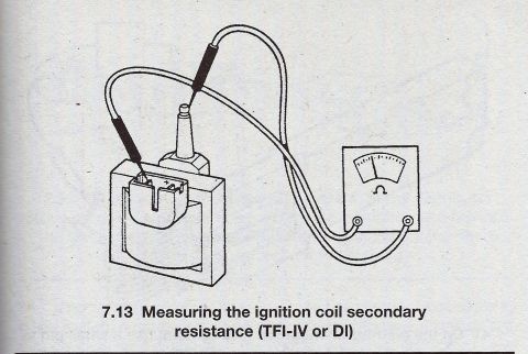
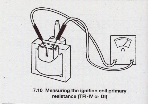
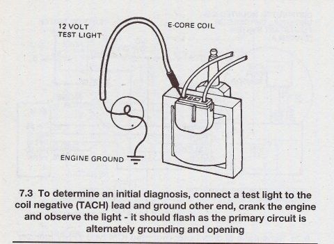








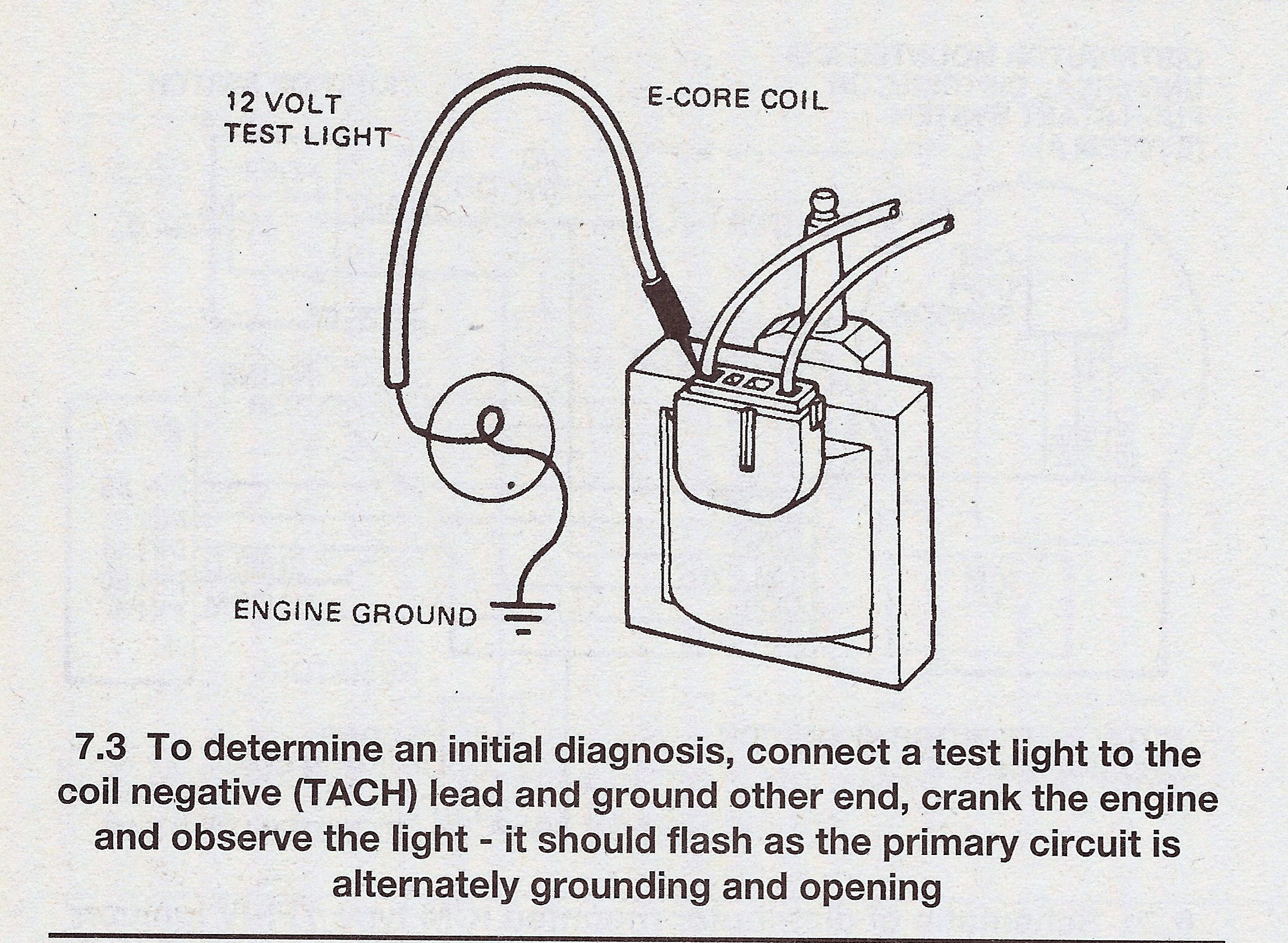
Service procedure step 7.3 showing a 12-volt test light connected to the E-core coil negative lead for ignition diagnosis.
Part of 1987-1991 Ford Bronco Service Procedures
This document is a single illustrated service procedure (figure 7.3) showing how to perform an initial diagnosis of a Ford TFI (Thick Film Ignition) E-core ignition coil using a 12-volt test light. The line drawing depicts an E-core coil with its connector, a 12-volt test light with its probe touching the coil's negative (TACH) lead terminal, and the test light's clip lead connected to an engine ground point. The caption instructs the technician to connect the test light to the coil negative (TACH) lead, ground the other end of the light, crank the engine, and observe the light: it should flash as the ignition primary circuit alternately grounds and opens. A flashing light indicates the ignition module is switching the coil primary circuit properly; no flash would point to a primary-side problem. The document contains no year, model, engine, or part-number information itself, it is a generic ignition diagnostic figure, uploaded as part of a set of ignition-related reference scans for a 1990 Ford Bronco, which uses the TFI ignition system this test applies to. It pairs with companion scans covering coil primary resistance, secondary resistance, and supply voltage tests.
Is this accurate? Sign in to help verify it.
Frequently asked questions
- How do I do an initial diagnosis of a TFI E-core ignition coil?
- Connect a 12-volt test light to the coil negative (TACH) lead, ground the other end of the test light to an engine ground, crank the engine, and observe the light.
- What should the test light do when cranking the engine during this test?
- The light should flash as the ignition primary circuit is alternately grounding and opening.
- Which coil terminal is the test light connected to?
- The coil negative lead, which is also labeled the TACH lead.
- Where is the other end of the test light connected?
- To an engine ground.






No comments yet.