Home/
Registry/
Ford/
Bronco/
1992-1996/
“pukin' dogII”/
Photo
supermotors.net/registry/media/877842
1996 Ford Bronco Seat Latch & Track Exploded Diagram (Ford R6480-D)

Reference · 1992-1996 BroncoAll 169 exploded parts diagrams


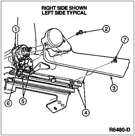
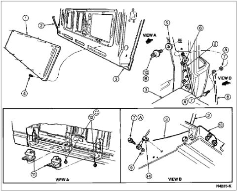
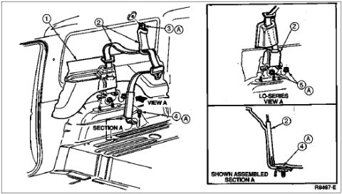





Exploded parts diagram of a power seat track and motor assembly with numbered component callouts.
Part of 1992-1996 Ford Bronco Exploded Parts Diagrams
This document is a single exploded-parts line drawing, labeled at the top with the note "RIGHT SIDE SHOWN, LEFT SIDE TYPICAL," indicating the illustrated right-side assembly mirrors the left side. The drawing depicts a mechanical latch and track/adjuster assembly (consistent with a seat latch and seat track mechanism, per the uploader's filename "Latch62648.jpg") mounted to a bracket, with a round knob or handle component at the upper portion and a slotted track rail running diagonally across the image. Seven numbered callouts (1 through 7) point to individual components: callout 1 indicates the latch mechanism at upper left, callout 2 a bolt or screw fastener at upper right, callout 3 the large panel/shield along the right side, callout 4 fasteners along the track (two arrows), callout 5 components within the latch/linkage area (two arrows), callout 6 a lower latch/bracket component, and callout 7 a small clip or fastener on the panel edge. The drawing carries the Ford illustration reference number R6480-D in the lower right corner. No legend, part numbers, torque values, or year/model text appears on the page, so component identification beyond callout numbers is not provided within the document itself.
Is this accurate? Sign in to help verify it.
Frequently asked questions
- Does this diagram show both the left and right side assemblies?
- It shows only the right side, but the note states "RIGHT SIDE SHOWN, LEFT SIDE TYPICAL," meaning the left side is a mirror image of what is illustrated.
- How many components are identified in the diagram?
- Seven numbered callouts (1 through 7) point to individual parts, including the latch mechanism, fasteners on the track, a bolt at the top, and the side panel/shield.
- Is there a parts legend or part numbers listed on this page?
- No. The page contains only the illustration with numbered callouts and the Ford figure reference R6480-D; no legend, part numbers, or torque specs are printed on it.
- What is the illustration reference number on this diagram?
- The figure reference in the lower right corner is R6480-D.






No comments yet.