Home/
Registry/
Ford/
Bronco/
1992-1996/
“pukin' dogII”/
Photo
supermotors.net/registry/media/877834
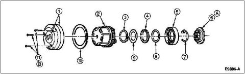
1996 Ford Bronco Dana 44 Automatic Locking Hub Exploded Diagram (E9606-A)

Reference · 1992-1996 BroncoAll 169 exploded parts diagrams
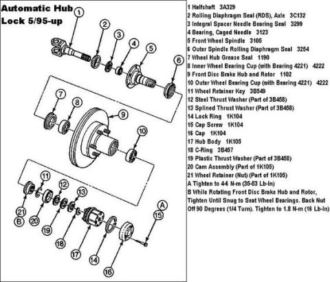












Exploded parts breakdown of a hub/clutch assembly with numbered seals, rings, bearings and snap rings.
Part of 1992-1996 Ford Bronco Exploded Parts Diagrams
This document is an exploded parts diagram, uploaded as depicting the automatic locking hub assembly for a Dana 44 front axle on a 1996 Ford Bronco. The illustration shows the hub components disassembled along a common centerline, identified only by numbered callouts 1 through 11 plus letter callouts A and B. From left to right, the drawing shows retaining screws (11, grouped under callout B), the outer hub cap/body (1), a large retaining ring (10), an internal geared cam/clutch assembly (2), a small retainer ring (3), thin washers/rings (9, 8), a spacer ring (4), a bearing or locknut assembly (5), a snap ring (7), and a splined nut or inner component (6, grouped under callout A). The figure carries the Ford illustration code E9606-A in the lower right corner. No text legend accompanies the drawing, so the specific part names, part numbers, and torque values for each callout are not provided in this scan. The diagram is useful for understanding the order of assembly/disassembly of the hub components, but a companion legend page would be needed to identify each numbered item by name.
Is this accurate? Sign in to help verify it.
Frequently asked questions
- What does this diagram show?
- An exploded view of a hub assembly with components laid out along a common axis, identified by callouts 1-11 plus letters A and B, and the figure code E9606-A.
- How many numbered components are identified in the diagram?
- Eleven numbered callouts (1 through 11), plus two lettered callouts (A and B) that group parts at each end of the assembly.
- Does the diagram include part names or part numbers?
- No. Only callout numbers/letters and the figure reference code E9606-A are visible; there is no legend or parts list on this page.
- What is the order of components in the exploded view?
- From left to right: screws (11/B), hub body (1), large ring (10), geared cam/clutch assembly (2), ring (3), washer (9), ring (4), washer (8), bearing/locknut assembly (5), snap ring (7), and splined component (6/A).






No comments yet.