SuperMotors SuperMotors SUPERMOTORS Search: try “orange Bronco on 35s”
Home/ Registry/ Ford/ Bronco/ 1987-1991/ “Eddie Bauer”/ Photo supermotors.net/registry/media/899376

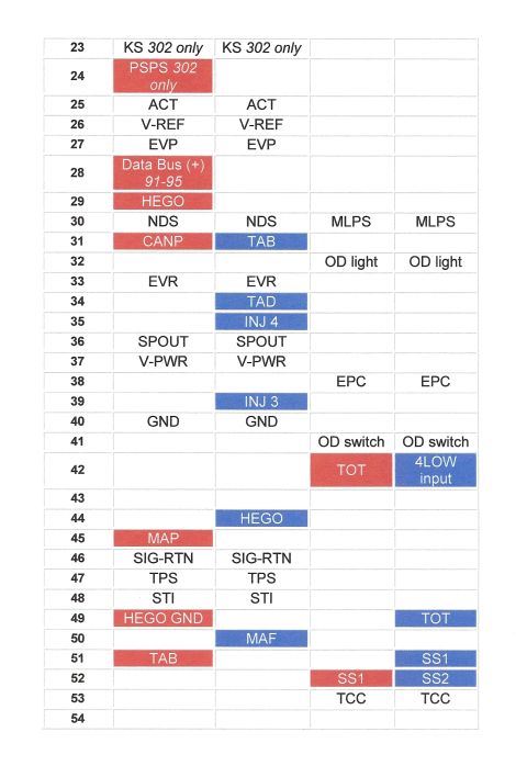
Ford Bronco SD to MAF EEC Pin-Out Chart Pins 23-54 - Speed Density Conversion

Ford computer EEC pin-out reference table with highlighted pins, rows 23-54
Ford computer EEC pin-out reference table with highlighted pins, rows 23-54Original file
Ford computer EEC pin-out reference table with highlighted pins, rows 23-54

Reference · 1987-1991 BroncoAll 53 manual pages
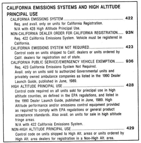
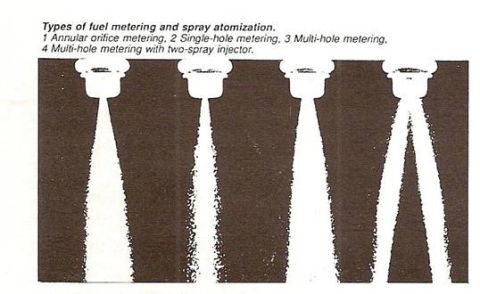
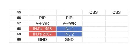
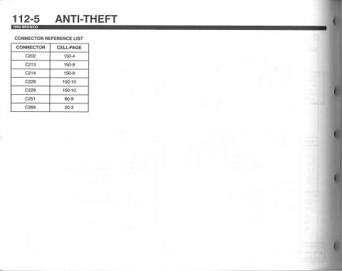
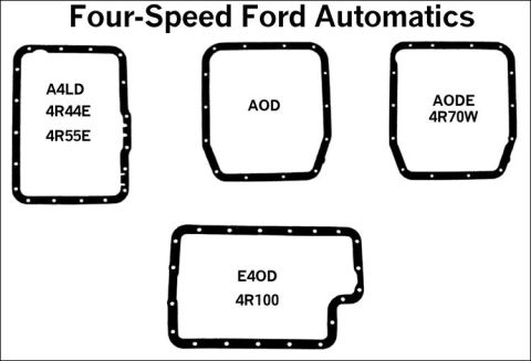
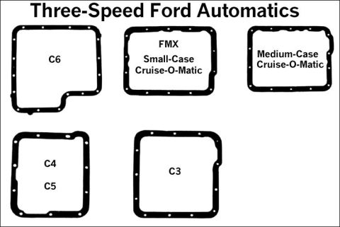
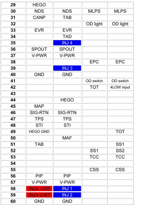
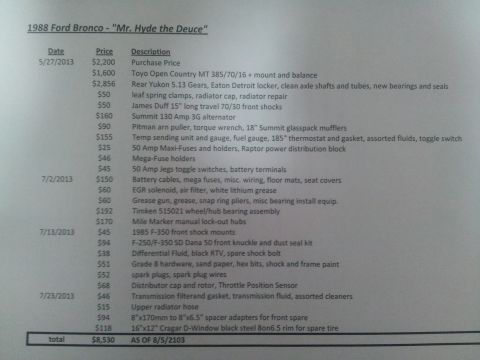
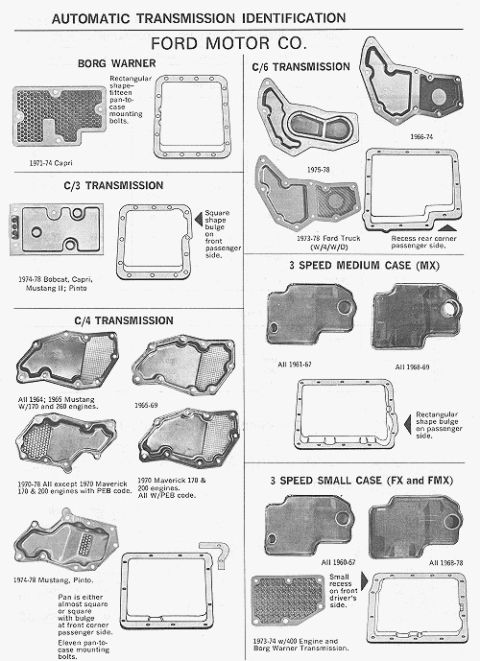
1990 order guide page listing California emissions and high altitude principal use codes 422, 93N, 423, 936, 4 Fuel Injector Spray Patterns Diagram - Annular, Single-Hole & Multi-Hole Metering Ford EEC SD to MAF Conversion Pin-Out Table Pins 55-60 - Injector, PIP, GND Ford Bronco SD to MAF EEC Pin-Out Chart Pins 23-54 - Speed Density Conversion '95 Bronco anti-theft connector reference list, manual page 112-5 Ford 4-Speed Automatic Transmission Pan ID Chart - AOD, AODE, E4OD, A4LD Ford Three-Speed Automatic Transmission Pan Gasket ID Chart - C3 C4 C5 C6 FMX Ford EEC-IV Computer Pin-Out Chart Pins 29-60 - Fuel Injector & Trans Signals Ford V8 camshaft application chart for 351W and 221-302 CI engines with duration, lift and lobe separation 1988 Ford Bronco Build Cost Sheet - "Mr. Hyde the Deuce" Parts & Expense List Ford automatic transmission identification chart of oil pan shapes for C3, C4, C6, MX, FX, FMX and Borg Warner 53manual pages1987-1991 Ford Bronco More reference 1973-1974 Ford Point-Type Ignition System Circuit Diagram - Coil & DistributorWiring diagram Ford Thermactor Air Bypass Valve Cutaway Diagram - Port IdentificationSchematic Ford Canister Purge Regulator Valve (CANP 9C915) Test Procedure - Figure 11Service procedure Ford 5.8L important engine information decal with 10° BTDC timing check and ASF-32C plugSpec plate Ford 5.0L V8 PCV Valve & Hose Routing Diagram - 9A474, 6B890, 6A664Exploded parts 1990 Bronco Major Standard Equipment sheet with interior features and functional specs by trimBrochure Borgeson Steering Intermediate Shaft Measurement Diagram - U-Joint Length B & CBlueprint Ford Thermactor Combination Valve Diagram - Air Bypass/Control Ports LabeledVacuum routing 1990 Ford Bronco Fuse Panel Diagram: Fuse Positions, Amps & Circuits (11-2)Fuse chart Ford V8 Intake Manifold Bolt Tightening Sequence Diagram - Stud LocationsTorque spec

Color-highlighted EEC computer pin-out reference table listing signal assignments for pins 23 through 54.

Part of 1987-1991 Ford Bronco Manual Pages

AI caption · Photo 945 of 1787

This document is one page of a multi-page EEC computer pin-out comparison table, apparently created to support a Speed Density (SD) to Mass Air Flow (MAF) EFI conversion on a Ford truck. The table lists ECU connector pins 23 through 54 across four columns, two engine-management columns (SD vs. MAF) and two transmission-related columns. For each pin it identifies the signal name, such as ACT, V-REF, EVP, NDS, CANP, TAB, TAD, EVR, SPOUT, V-PWR, INJ 3, INJ 4, GND, HEGO, MAP, MAF, SIG-RTN, TPS, STI, HEGO GND, MLPS, OD light, OD switch, EPC, TOT, 4LOW input, SS1, SS2 and TCC. Color highlighting distinguishes pins that differ between the two systems: red-highlighted cells (e.g., PSPS 302 only, Data Bus (+) 91-95, HEGO, CANP, MAP, HEGO GND, TAB, TOT, SS1) appear in one column, while blue-highlighted cells (e.g., TAB, TAD, INJ 4, INJ 3, HEGO, MAF, 4LOW input, TOT, SS1, SS2) appear in the other, showing which pins move or change function. Notes indicate some pins apply to the 302 engine only (KS, PSPS) and Data Bus (+) applies to 1991-95. Column headers are on another page of the set.

Is this accurate? Sign in to help verify it.

Frequently asked questions

What ECU pins are shown on this page?
Pins 23 through 54, with signal assignments listed in four columns comparing two configurations plus transmission-related pins.
Which pins are noted as 302 engine only?
Pin 23 (KS) is marked '302 only' in both engine columns, and pin 24 (PSPS) is marked '302 only'.
Where does the MAF sensor signal connect according to this chart?
MAF is shown on pin 50 in the MAF-column (highlighted blue), while the SD column shows MAP on pin 45 (highlighted red).
Which pin carries the Data Bus (+) signal and for what years?
Pin 28 is labeled 'Data Bus (+) 91-95' in the first column.
What transmission-related signals are listed?
MLPS (pin 30), OD light (pin 32), EPC (pin 38), OD switch (pin 41), TOT (pins 42/49), 4LOW input (pin 42), SS1 (pins 51/52), SS2 (pin 52), and TCC (pin 53).


Comments

No comments yet.

More 1987-1991 Broncos