SuperMotors SuperMotors SUPERMOTORS Search: try “orange Bronco on 35s”
Home/ Registry/ Ford/ Bronco/ 1992-1996/ “Big '92”/ Photo supermotors.net/registry/media/919652

Ford Bronco Alternator Charge Wire Test - C202 Connector Pin 42 LG/R Diagram

Wiring diagram of C202 firewall connector charge wire to alternator with DVOM and ground for voltage drop testing
Wiring diagram of C202 firewall connector charge wire to alternator with DVOM and ground for voltage drop testingOriginal file
Wiring diagram of C202 firewall connector charge wire to alternator with DVOM and ground for voltage drop testing

Reference · 1992-1996 BroncoAll 411 wiring diagrams

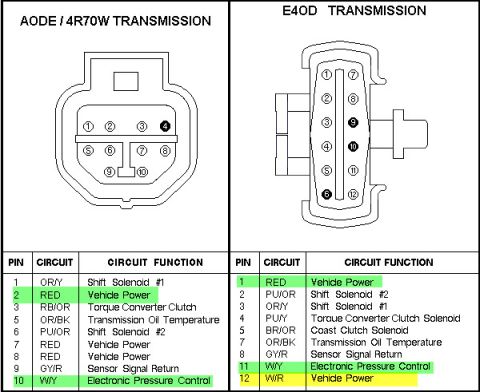
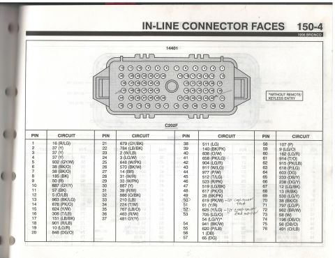
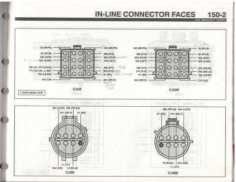
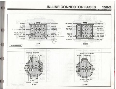
Gas engine C101M and C101F connector pin layouts with circuit and wire color table C101F and C101M bulkhead connector pinouts with pin and circuit tables, Temp and Oil Press marked Ford Bronco Power Window & Door Lock Wiring Diagram - Circuit Breaker 14, G201 Ford Bronco Alternator Charge Wire Test - C202 Connector Pin 42 LG/R Diagram Ford Bronco Alternator Charge Wire Diagram - C202 Pin 42 LG/R Wire Test Bosch Relay Wiring Diagram - Pin 30, 85, 86, 87, 87a Explained (SPST Relay) Ford 3G Alternator Wiring Diagram - Mega Fuse, Charge Lamp & Regulator Pinout Ford AODE/4R70W & E4OD Transmission Connector Pinout - Wire Colors & Functions 1996 Ford Bronco C202F 76-Pin Connector Pinout - EVTM Page 150-4 1994 Ford Bronco/F-Series C103 & C108 Connector Pinouts - EVTM Page 150-2 1994 Ford Bronco/F-Series EVTM 150-2: C103 & C108 In-Line Connector Pinouts Ford Bronco VSS to PCM Wiring Diagram - Rear Axle Sensor, PSOM, ABS Circuit 411wiring diagrams1992-1996 Ford Bronco More reference Ford BW 1356 Manual Shift Transfer Case Exploded Diagram - Bronco & F-150Exploded parts 4WD truck alignment sleeve install instructions with knuckle illustration and camber/caster top viewsService procedure Homelite Textron SAFE-T-TIP anti-kickback chain saw device installation and use instruction sheetManual page 5-Pin SPDT Relay Diagram - Pin 30/85/86/87/87a Wiring & CarPC ACC/IGN SetupSchematic Ford Bronco Gasoline Engine Vacuum Hose Routing Diagram - Hose Colors & PortsVacuum routing Ford Bronco Power Distribution Box Diagram - Relay Layout & Fuse PositionsFuse chart 1994 Ford Bronco Door Data Spec Plate - VIN, GVWR, Axle & Paint CodesSpec plate Smittybilt XRC Gen 3 Winch Box - 9.5K/12K Recovery Winch Features & CalloutsBrochure Brake Booster to Master Cylinder Adapter Plate Blueprint - Ford Bronco SwapBlueprint Rod Bolt Stretch Monitoring Chart - 8-Rod V8 Connecting Rod Bolt Record SheetTorque spec

Wiring diagram showing C202 connector charge wire to the alternator, with DVOM and ground connections for charging voltage-drop testing.

Part of 1992-1996 Ford Bronco Wiring Diagrams

AI caption · Photo 1085 of 2193

This document is a simple hand-drawn/computer-drawn wiring test diagram showing how to check the alternator charge wire circuit on a Ford vehicle. On the left is a detailed illustration of the C202 connector, described as the firewall connector (male side), with its pin grid shown and 'TOP' marked for orientation. A red test lead runs from Pin 42 of the C202 connector, identified as the LG/R (light green/red) wire to the alternator, up to a DVOM (digital volt-ohm meter). The DVOM's other lead goes to Ground. From Pin 42, the charge wire (colored yellow-green in the drawing and labeled 'Charge wire LG/R') routes through a weatherpack connector and continues to the Alternator, drawn as a box on the right. The diagram teaches a reader which pin (Pin 42) and wire color (LG/R) carry the alternator charge/sense signal through the C202 firewall connector, where the inline weatherpack connector sits in that circuit, and how to hook up a DVOM between Pin 42 and ground to test continuity/voltage on the charge wire. It appears to be page two of a two-part 'Charge diagram' set uploaded for a 1992 Ford Bronco.

Is this accurate? Sign in to help verify it.

Frequently asked questions

Which pin on the C202 connector is the alternator charge wire?
Pin 42, which is the LG/R (light green/red) wire going to the alternator.
What is the C202 connector in this diagram?
It is the firewall connector, male side, shown with its pin grid and 'TOP' marked for orientation.
How is the DVOM connected to test the charge wire?
One DVOM lead connects to Pin 42 of the C202 connector (the LG/R wire to the alternator) and the other lead goes to ground.
Is there an inline connector in the charge wire between the firewall and alternator?
Yes, the diagram shows a weatherpack connector in the LG/R charge wire between the C202 connector and the alternator.
What color is the alternator charge wire in this diagram?
LG/R (light green/red), labeled both at Pin 42 and along the run to the alternator as 'Charge wire LG/R'.


Comments

No comments yet.

More 1992-1996 Broncos