1990 Ford Bronco Instrument Cluster Troubleshooting Hints (60-8) - Gauges & Tach
Reference · 1987-1991 BroncoAll 95 service procedures













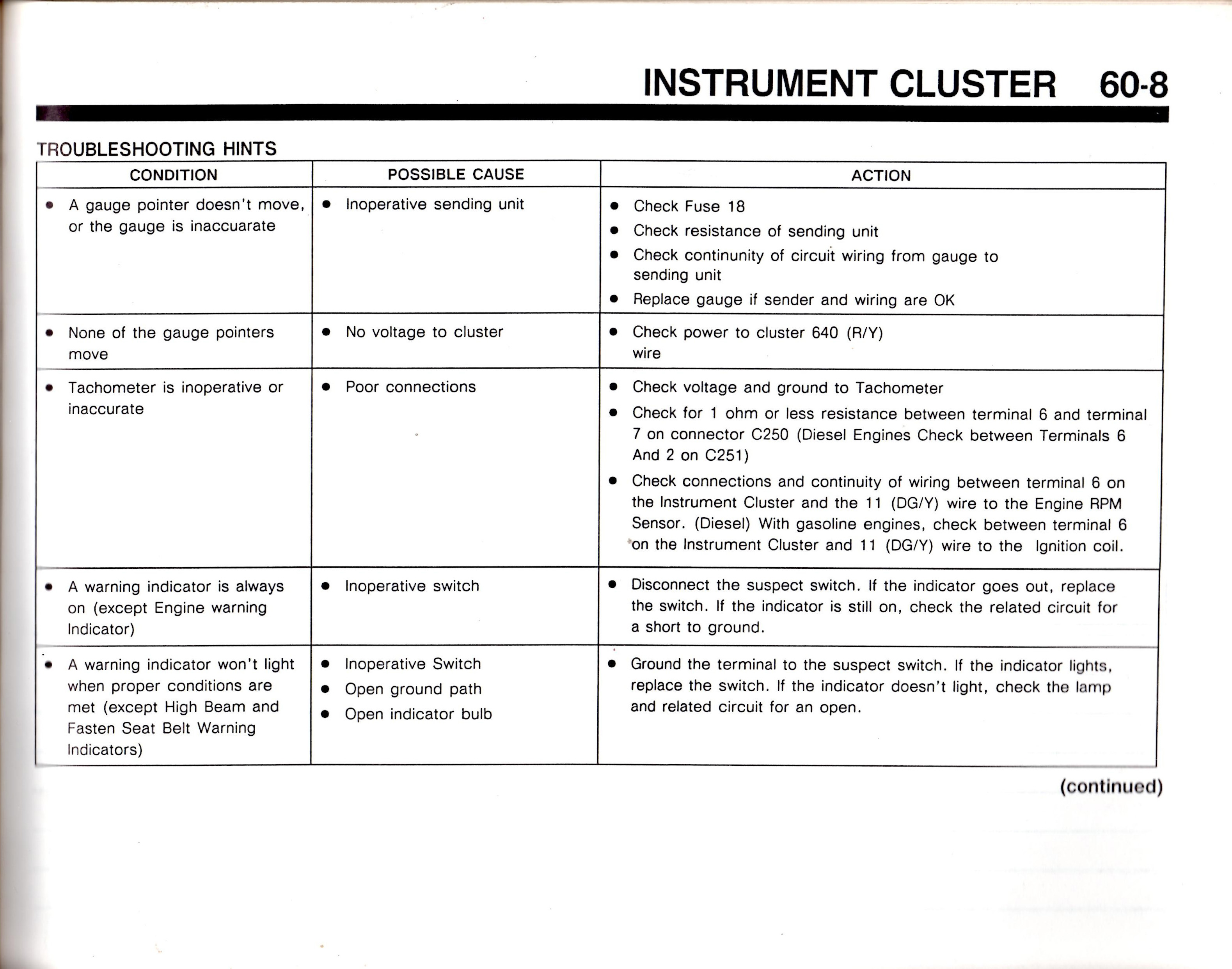
Shop manual troubleshooting chart (60-8) for instrument cluster: gauge-not-moving, no-cluster-voltage, inoperative tachometer and warning-indicator conditions with causes and actions (check fuse 18).
Part of 1987-1991 Ford Bronco Service Procedures
This is page 60-8 of a Ford service manual section covering the Instrument Cluster, presenting a Troubleshooting Hints table with three columns: Condition, Possible Cause, and Action. It covers five fault conditions: a single gauge pointer not moving or reading inaccurately (inoperative sending unit, check Fuse 18, sender resistance, circuit continuity, or replace the gauge); no gauge pointers moving (no voltage to cluster, check power on the 640 R/Y wire); an inoperative or inaccurate tachometer (poor connections, check voltage and ground, verify 1 ohm or less between terminals 6 and 7 on connector C250, or terminals 6 and 2 on C251 for diesel engines, and check continuity of the 11 DG/Y wire to the engine RPM sensor on diesels or to the ignition coil on gasoline engines); a warning indicator that stays on (inoperative switch, disconnect the suspect switch and test); and a warning indicator that won't light (inoperative switch, open ground path, or open bulb, ground the switch terminal to test). The page is marked '(continued)', indicating additional troubleshooting hints follow on the next page. Uploaded as part of a 1990 Ford Bronco documentation set.
Is this accurate? Sign in to help verify it.
Frequently asked questions
- What should I check if one gauge in my instrument cluster doesn't move or is inaccurate?
- The likely cause is an inoperative sending unit. Check Fuse 18, check the resistance of the sending unit, check continuity of the circuit wiring from the gauge to the sending unit, and replace the gauge if the sender and wiring are OK.
- Why don't any of my gauge pointers move?
- The possible cause is no voltage to the cluster. Check power to the cluster on the 640 (R/Y) wire.
- How do I troubleshoot an inoperative or inaccurate tachometer?
- Check voltage and ground to the tachometer; check for 1 ohm or less resistance between terminal 6 and terminal 7 on connector C250 (diesel engines: between terminals 6 and 2 on C251); and check connections and continuity between terminal 6 on the instrument cluster and the 11 (DG/Y) wire to the engine RPM sensor (diesel) or to the ignition coil (gasoline engines).
- What do I do if a warning indicator stays on all the time?
- Disconnect the suspect switch. If the indicator goes out, replace the switch. If the indicator is still on, check the related circuit for a short to ground. (This applies except for the Engine warning indicator.)
- How do I test a warning indicator that won't light?
- Ground the terminal to the suspect switch. If the indicator lights, replace the switch. If it doesn't light, check the lamp and related circuit for an open. Possible causes are an inoperative switch, open ground path, or open indicator bulb.






No comments yet.