MSD Noise Filter Capacitor PN 8830 Install Diagram - MSD 6AL Ignition Wiring

Reference · 1987-1991 BroncoAll 95 service procedures
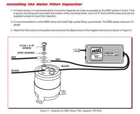








Service procedure for installing the MSD noise filter capacitor, with numbered mounting/wiring steps and a figure showing red and black lead connections.
Part of 1987-1991 Ford Bronco Service Procedures
This document is an installation instruction page for the MSD Noise Filter Capacitor, part number 8830, used with MSD ignition control boxes such as the MSD 6AL (part no. 6420). It provides three installation steps: (1) mount the capacitor as close as possible to the MSD Ignition Control by marking mounting holes, drilling with a 3/16" bit, and using the supplied screws; (2) cut the MSD wires and install high-quality ring lug terminals, noting the MSD power wires are 12-gauge; and (3) attach the red wires to the positive terminal and the black wires to the negative terminal as illustrated. Figure 3 shows an exploded view of the terminal hardware, a 10-32 x 3/8" screw and star washer securing two ring terminals to the capacitor's positive post, with the red and black wires from both the vehicle and the MSD 6AL box routed to the capacitor's + and - terminals respectively. The MSD 6AL box in the illustration bears manufacturer info for Autotronic Controls Corporation of El Paso, TX. This procedure helps suppress electrical noise/RFI in ignition systems using MSD multiple-spark discharge boxes.
Is this accurate? Sign in to help verify it.
Frequently asked questions
- How do I wire the MSD Noise Filter Capacitor PN 8830?
- Attach the red wires to the positive terminal and the black wires to the negative terminal of the capacitor, as shown in Figure 3. Ring lug terminals are secured with a 10-32 x 3/8" screw and star washer.
- Where should the noise filter capacitor be mounted?
- As close as possible to the MSD Ignition Control. Find a secure mounting point, mark the mounting holes, drill with a 3/16" bit, and mount with the supplied screws.
- What gauge are the MSD power wires?
- The MSD power wires are 12-gauge. It is recommended to cut them and install high-quality ring lug terminals.
- What MSD ignition box is shown in the diagram?
- The MSD 6AL Multiple Spark Discharge box, part number 6420, made by Autotronic Controls Corporation of El Paso, TX.
- What hardware secures the ring terminals to the capacitor?
- A 10-32 x 3/8" screw with a star washer, as shown in the exploded view in Figure 3.






No comments yet.