SuperMotors SuperMotors SUPERMOTORS Search: try “orange Bronco on 35s”
Home/ Registry/ Ford/ Bronco/ 1987-1991/ “Eddie Bauer”/ Photo supermotors.net/registry/media/962993

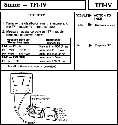
TFI-IV stator resistance test chart with ohmmeter and TFI module…
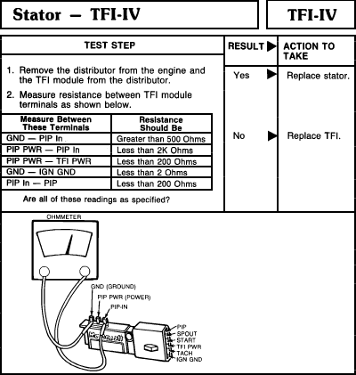
TFI-IV stator resistance test chart with ohmmeter and TFI module terminal illustration
TFI-IV stator resistance test chart with ohmmeter and TFI module terminal illustrationOriginal file
TFI-IV stator resistance test chart with ohmmeter and TFI module terminal illustration

Reference · 1987-1991 BroncoAll 95 service procedures

Tuff Stuff Ford PMGR Starter Install Instructions 6124 6131 6132 - Wiring Russell Speed Bleeder three-step brake bleeding instructions with illustrated steps MSD Noise Filter Capacitor PN 8830 Install Diagram - MSD 6AL Ignition Wiring TFI-IV stator resistance test chart with ohmmeter and TFI module terminal illustration 1990 Ford Bronco Instrument Cluster Troubleshooting 60-9 - Voltmeter & Warning 1990 Ford Bronco Instrument Cluster Troubleshooting Hints (60-8) - Gauges & Tach Ford Racing Idle Setting Procedure Instruction Sheet IS-1850-0156 - TPS & IAC Throttle body service procedure decal warning not to clean inside or turn set screw CCW 95service procedures1987-1991 Ford Bronco More reference 1973-1974 Ford Point-Type Ignition System Circuit Diagram - Coil & DistributorWiring diagram Ford Thermactor Air Bypass Valve Cutaway Diagram - Port IdentificationSchematic Ford 5.8L important engine information decal with 10° BTDC timing check and ASF-32C plugSpec plate Ford 5.0L V8 PCV Valve & Hose Routing Diagram - 9A474, 6B890, 6A664Exploded parts Ford 5.0L/5.8L Air Throttle Body Assembly Diagram - Canister Purge Ports & TPSManual page 1990 Bronco Major Standard Equipment sheet with interior features and functional specs by trimBrochure Borgeson Steering Intermediate Shaft Measurement Diagram - U-Joint Length B & CBlueprint Ford Thermactor Combination Valve Diagram - Air Bypass/Control Ports LabeledVacuum routing 1990 Ford Bronco Fuse Panel Diagram: Fuse Positions, Amps & Circuits (11-2)Fuse chart Ford V8 Intake Manifold Bolt Tightening Sequence Diagram - Stud LocationsTorque spec

TFI-IV stator test step listing resistance specs between TFI module terminals, with replace stator or replace TFI actions and ohmmeter hookup.

Part of 1987-1991 Ford Bronco Service Procedures

AI caption · Photo 1487 of 1787

Stator TFl-lV TFl-lV rm svzr mun ACYION m uK: Rammeudmnbmovlmmlhevwmemd _5 B H, mmmwmmmmmnmw ' R w " 2 Mluum "mum bmwem m mm mmm u mmm [mew 0... mn- mm _ my m ammm 5w Ohm "" > "9' 7 w pm 7 up m m; m. 2x om, w MR 7 m m: m. Inv- 2111: um on 7IGN mm m; m. 2 an." w n 7 W Lu: m... 200 mm; in in mm". yuan-v; a 39mm

Is this accurate? Sign in to help verify it.

Comments

No comments yet.

More 1987-1991 Broncos