1993-1994 Ford Probe 2.5L Cooling Fan Wiring Diagram - Relays, PCM & Fuses
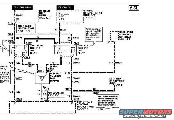
Wiring diagram of the 2.5L electric cooling fan low/high speed relay circuits with color-coded wires and connectors.
This is a scanned wiring diagram page for the electric engine cooling fan circuit of a 2.5L-engine vehicle (uploaded to a 1993 Ford Probe gallery; filename suggests a 1994 diagram). It shows power flowing from two sources: a 15A ENGINE fuse in the interior fuse panel (hot in start or run, see page 13-7) and a 40A COOLING FAN fuse in the engine compartment fuse box (hot at all times, page 13-3, via circuit 15 BK/R). The diagram details the low-speed cooling fan relay (connector C167) and high-speed cooling fan relay (connector C144), which feed the electric cooling fan motor through connector C118 using wires 169 BL/Y, 171 BL/BK, BR/O, and BR/Y. The motor grounds through 50 BK to G103 (see grounds page 10-6). Relay control circuits 173 BL/GN run through splices S190 and S192 and connector C107 to the Data Link Connector (DLC, C133) and to the Powertrain Control Module (PCM, connectors C246/C247, page 25-6). A 173 BL/GN branch also feeds the high-speed condenser fan relay via C164 (page 54-4). Notes explain the high-speed relay directs voltage for high-speed fan operation and that the PCM uses sensor/actuator information to control powertrain operation. Circuit 174 R/W and 40 BK/W / 16 R power feeds are also labeled.
Is this accurate? Sign in to help verify it.
Frequently asked questions
- What fuses power the cooling fan circuit on the 2.5L Probe?
- A 15A ENGINE fuse in the interior fuse panel (hot in start or run, page 13-7) and a 40A COOLING FAN fuse in the engine compartment fuse box (hot at all times, page 13-3, circuit 15 BK/R).
- Which relays control the electric cooling fan?
- A low speed cooling fan relay (connector C167) and a high speed cooling fan relay (connector C144). When energized, the high speed relay directs voltage to the fan motor to operate at high speed.
- What wire colors connect to the electric cooling fan motor?
- Circuit 169 BL/Y and 171 BL/BK feed into connector C118 as BR/O and BR/Y wires; the motor grounds through a GY wire to circuit 50 BK at ground G103.
- How does the PCM connect to the cooling fan relays?
- Control circuits 173 BL/GN run through splices S190 and S192 and connector C107 to the PCM (via connectors C246 and C247, page 25-6) and also to the Data Link Connector (DLC) at C133.
- Where does the high speed condenser fan relay tie into this circuit?
- A 173 BL/GN wire branches through connector C164 to the high speed condenser fan relay, referenced on page 54-4.
Comments
More from this build





No comments yet.