1996 Ford Probe Instrument Cluster Wiring Diagram - Fuel & Temp Gauge Circuits
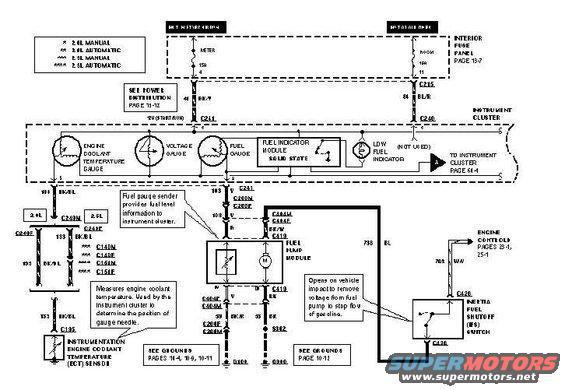
Wiring diagram of the instrument cluster fuel gauge, temperature gauge, and fuel pump module circuits with color-coded wires.
This scanned wiring diagram covers the instrument cluster fuel and temperature gauge circuits for a Ford Probe (uploaded as a '1996 CLUSTER' page). It shows two power feeds: a METER 15A fuse (position 4) hot in start/run and a ROOM 10A fuse (position 11) hot at all times, both from the interior fuse panel (page 13-7). The instrument cluster contains the engine coolant temperature gauge, voltage gauge, fuel gauge, a solid-state fuel indicator module, and a low fuel indicator, with a reference to instrument cluster page 61-4. The fuel gauge connects through circuit 103 (V, then R) via connectors C241, C200M/F, and C244M/F to the fuel pump module, whose sender provides fuel level information. The ECT sensor connects via circuit 133 BK/BL through connectors that vary by engine (2.0L manual/automatic and 2.5L manual/automatic variants noted in the legend, using C249M/F, C140M/F, C151M/F, and C195). Grounds route to G109 and G300 via S302. The inertia fuel shutoff (IFS) switch (connector C426, circuit 738 BL) opens on vehicle impact to cut voltage to the fuel pump; circuit 703 continues to engine controls (pages 25-1). The diagram identifies wire colors, circuit numbers, connector IDs, and page cross-references useful for gauge and fuel pump diagnostics.
Is this accurate? Sign in to help verify it.
Frequently asked questions
- What fuses power the instrument cluster gauges in this diagram?
- A 15A METER fuse (position 4, hot in start/run) and a 10A ROOM fuse (position 11, hot at all times), both in the interior fuse panel shown on page 13-7.
- What wire color and circuit connects the fuel gauge to the fuel pump module?
- Circuit 103, violet (V) from the cluster through connector C241, becoming red (R) through C200M/C200F and C244M/C244F to the fuel pump module at C419.
- What does the inertia fuel shutoff (IFS) switch do?
- Per the diagram callout, it opens on vehicle impact to remove voltage from the fuel pump and stop the flow of gasoline. It connects via connector C426 on circuit 738 BL.
- How does the engine coolant temperature gauge get its signal?
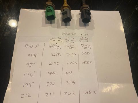
- Through circuit 133 BK/BL from the instrumentation engine coolant temperature (ECT) sensor at connector C195; the callout says the sensor's reading is used by the cluster to position the gauge needle. Connector routing varies by engine (2.0L/2.5L, manual/automatic).
- Where does the fuel pump module ground?
- One ground path goes through C404F/C404M and C206F/C206M in BK/W wire to G109 (grounds pages 14-4, 10-9, 10-11); another goes via circuit 55 BK through splice S302 to G300 (grounds page 10-12).
Comments
More from this build







No comments yet.