SuperMotors SuperMotors SUPERMOTORS Search: try “orange Bronco on 35s”
Home/ Registry/ Ford/ Bronco/ 1987-1991/ “Cookie Monster”/ Photo supermotors.net/registry/media/95940

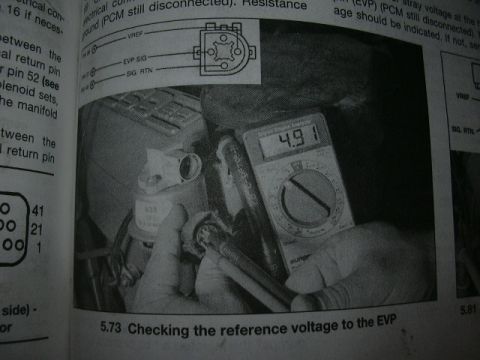
Ford Bronco EGR Valve Position (EVP) Sensor Connector Pinout Diagram
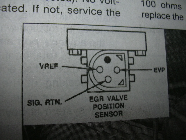
Scanned manual page showing EGR valve position sensor connector pinout with VREF, EVP, SIG RTN
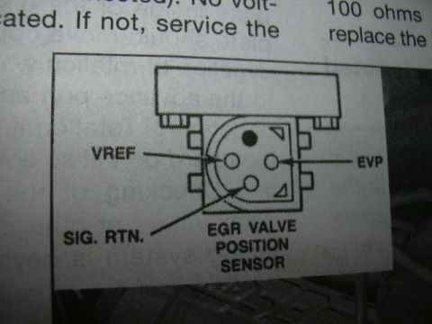
Scanned manual page showing EGR valve position sensor connector pinout with VREF, EVP, SIG RTNOriginal file
Scanned manual page showing EGR valve position sensor connector pinout with VREF, EVP, SIG RTN

Reference · 1987-1991 BroncoAll 53 manual pages
Ford Bronco EGR Valve Position (EVP) Sensor Connector Pinout Diagram Ford 5.0L/5.8L Air Throttle Body Assembly Diagram - Canister Purge Ports & TPS Ford 5.0L/5.8L EFI Air Throttle Body Assembly Diagram - TPS & Air Bypass Valve Ford Engine/Emissions-Diagnosis 1990 Shop Manual cover Ford V8 camshaft application chart for 351W and 221-302 CI engines with duration, lift and lobe separation Speed control troubleshooting hints table 31-5 with conditions, causes and resistance checks Instrument panel parts list with item numbers, part numbers and descriptions Ford Racing mass air conversion kits chart, M-9000-A51, B50, T50 and T51 Ford DSO and wheelbase code chart for Bronco, E-150-250-350 and F-150-250-350 and F-Super Duty 1988 Ford Bronco Build Cost Sheet - "Mr. Hyde the Deuce" Parts & Expense List Ford automatic transmission identification chart of oil pan shapes for C3, C4, C6, MX, FX, FMX and Borg Warner 1990 Ford Bronco/F-Series Oil Pressure Gauge Specs & Sender Location 33-32-4 53manual pages1987-1991 Ford Bronco More reference Manual photo 5.73 checking reference voltage to the EVP sensor with a multimeter reading 4.91Service procedure Ford 3G Alternator Wiring Diagram - Mega Fuse, Charge Lamp & Wire ColorsWiring diagram Ford 5.0 Fox Mustang Short Belt Routing Diagram - 84.5" & 70.5" vs StockSchematic Welder Input Data Plate - Serial JH229505, Stock 901782, 200/230/460V SpecsSpec plate Ford 5.0L V8 PCV Valve & Hose Routing Diagram - 9A474, 6B890, 6A664Exploded parts Magnum Metropolitan Brochure - Ford Bronco/F-Series Suburban-Style ConversionBrochure Tubing Adapter Blueprint 2.00" OD x 1.375" ID x 3" - 1.125"-12 TPI RH ThreadBlueprint '89 Ford vehicle emission control information label with EEC IV/EFI timing steps and vacuum hose routingVacuum routing 1990 Ford Bronco Fuse Panel Diagram: Fuse Positions, Amps & Circuits (11-2)Fuse chart Ford V8 Intake Manifold Bolt Tightening Sequence Diagram - Stud LocationsTorque spec

Scanned service manual page diagramming the EGR valve position sensor connector terminals with diagnostic text.

Part of 1987-1991 Ford Bronco Manual Pages

AI caption · Photo 381 of 1913

This scanned manual page shows a connector pinout diagram for a Ford EGR Valve Position (EVP) Sensor, uploaded to the gallery of a 1991 Ford Bronco. The illustration depicts the face of the three-pin sensor connector mounted on top of the EGR valve, with each terminal identified by a callout arrow: VREF (reference voltage) on the upper-left pin, EVP (position signal output) on the right pin, and SIG. RTN. (signal return/ground) on the lower pin. The diagram is captioned "EGR VALVE POSITION SENSOR." Fragments of surrounding diagnostic text are visible at the top of the page, mentioning "100 ohms" and instructions to "service the" or "replace the" a component, indicating this figure accompanies an EVP sensor testing procedure (likely resistance/voltage checks), though the full test text is cut off. A reader can use this diagram to identify which terminal is which when probing the EVP sensor connector during diagnosis, for example, to check reference voltage on VREF, signal output on EVP, and continuity to ground on SIG. RTN. No year, model, engine, wire colors, or part numbers are visible on the page itself.

Is this accurate? Sign in to help verify it.

Frequently asked questions

What are the three pins on the Ford EVP (EGR Valve Position) sensor connector?
According to the diagram, the three pins are VREF (upper-left), EVP (right), and SIG. RTN. (lower).
Which pin on the EGR position sensor is the signal output?
The pin labeled EVP, shown on the right side of the connector in the diagram, is the EGR valve position signal.
Which terminal is the reference voltage on the EVP sensor?
The terminal labeled VREF, located at the upper-left of the connector face in the diagram.
Where is the signal return (ground) pin on the EVP sensor connector?
SIG. RTN. is the lower pin on the connector face, as indicated by the callout arrow in the diagram.


Comments

No comments yet.

More 1987-1991 Broncos