Home/
Registry/
Ford/
Bronco/
1987-1991/
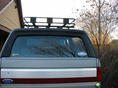
“Cookie Monster”/
Photo
supermotors.net/registry/media/95939
Ford EVP Sensor Test - EGR Valve Position Sensor Resistance & Pinout Diagram
Reference · 1987-1991 BroncoAll 95 service procedures
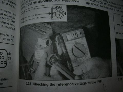
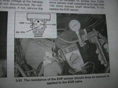


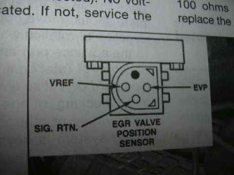









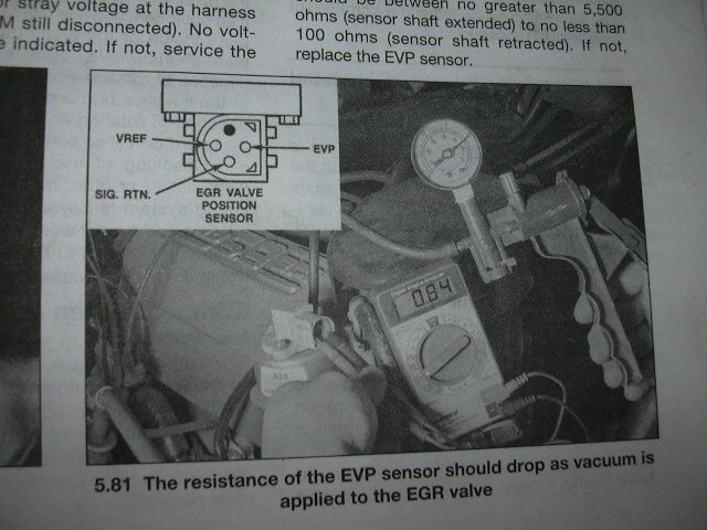
Service-manual page and photo showing the EVP (EGR valve position) sensor test: resistance should drop from ~5,500 ohms (shaft extended) to ~100 ohms (retracted) as vacuum is applied to the EGR valve.
Part of 1987-1991 Ford Bronco Service Procedures
This is a scanned page from an automotive service manual (likely a Haynes-style repair guide) showing a diagnostic test procedure for the EGR Valve Position (EVP) sensor. The page includes a photograph (figure 5.81) of a hand-held vacuum pump with gauge applied to the EGR valve while a digital multimeter (displaying a reading of 084) measures the EVP sensor's resistance. An inset diagram identifies the three terminals of the EGR Valve Position Sensor connector: VREF, EVP, and SIG. RTN. (signal return). The visible instructional text states that the sensor's resistance should be between no greater than 5,500 ohms with the sensor shaft extended and no less than 100 ohms with the sensor shaft retracted; if the readings fall outside this range, the EVP sensor should be replaced. The caption explains that the resistance of the EVP sensor should drop as vacuum is applied to the EGR valve. Partial text at the top left references checking for stray voltage at the harness with a module still disconnected. A reader can learn the EVP sensor pinout, the acceptable resistance range, and the vacuum-application test method for verifying EVP sensor operation.
Is this accurate? Sign in to help verify it.
Frequently asked questions
- What are the terminals on the EGR Valve Position (EVP) sensor connector?
- The inset diagram labels three terminals: VREF, EVP, and SIG. RTN. (signal return).
- What resistance readings should the EVP sensor show?
- The resistance should be no greater than 5,500 ohms with the sensor shaft extended and no less than 100 ohms with the sensor shaft retracted. If not, replace the EVP sensor.
- How should the EVP sensor's resistance behave when vacuum is applied to the EGR valve?
- Per figure 5.81, the resistance of the EVP sensor should drop as vacuum is applied to the EGR valve.
- What should be done if the EVP sensor resistance is out of specification?
- The document states to replace the EVP sensor if the resistance readings are not within the specified range.





No comments yet.