Ford 5.0L Thermactor Air Pump, Bypass Valve & Silencer Diagram - 1990 Bronco
Reference · 1987-1991 BroncoAll 111 schematics
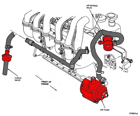
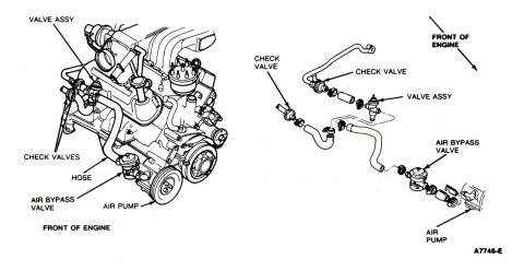
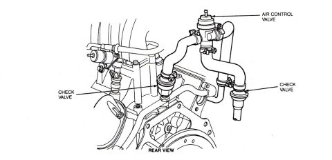
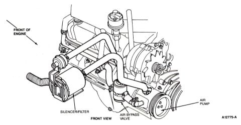
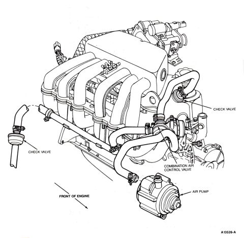
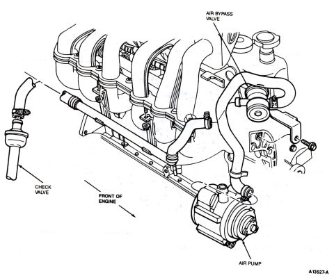
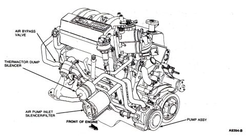
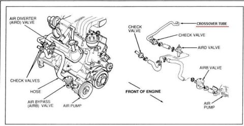
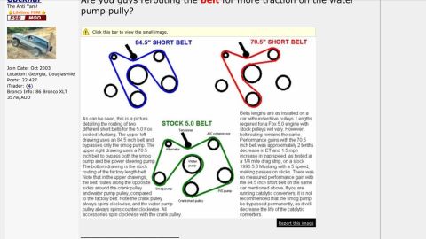
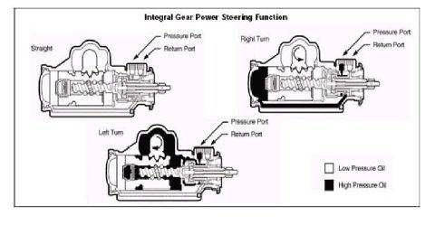
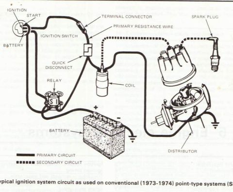









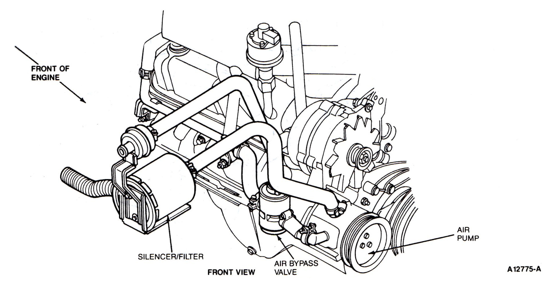
Secondary air schematic (front view) showing the silencer/filter, air bypass valve and air pump plumbing.
Part of 1987-1991 Ford Bronco Schematics
This document is a factory-style line drawing (schematic) showing the front view of a Ford V8 engine's Thermactor secondary air injection (emissions) system components. The illustration is labeled 'FRONT VIEW' with an arrow indicating 'FRONT OF ENGINE.' Four callouts identify key components: the SILENCER/FILTER mounted on the left side of the engine front, the AIR BYPASS VALVE located low near the center-front of the engine with associated hose routing, and the belt-driven AIR PUMP with its pulley at the lower right of the accessory drive. The drawing also depicts the alternator, valve cover, EGR-type valve at the top, and the air hose plumbing connecting the pump, bypass valve, and silencer/filter, though these are not labeled. A drawing reference number 'A12775-A' appears at the lower right. A reader can learn where the secondary air pump, air bypass valve, and silencer/filter are physically located on the front of the engine and how the air hoses route between them, which is useful for identifying, diagnosing, or replacing Thermactor/smog pump emissions components. The document itself carries no year, model, or engine displacement text; the uploader attributes it to a 1990 Ford Bronco 5.0L.
Is this accurate? Sign in to help verify it.
Frequently asked questions
- Where is the air pump located on the front of the engine?
- The diagram shows the air pump at the lower right of the engine front, driven by a belt on a pulley in the accessory drive area.
- Where is the air bypass valve located?
- The air bypass valve is shown mounted low near the center-front of the engine, below the air hose routing and next to the air pump.
- What is the silencer/filter and where is it mounted?
- The silencer/filter is a canister-shaped component shown mounted at the front-left of the engine, connected by a ribbed hose, as labeled in the diagram.
- What view does this diagram show?
- It is labeled 'FRONT VIEW' with an arrow indicating the 'FRONT OF ENGINE' orientation.
- Is there a reference number on this diagram?
- Yes, the drawing carries the reference number A12775-A in the lower right corner.






No comments yet.