Home/
Registry/
Ford/
Bronco/
1987-1991/
1990 Ford Bronco/
Photo
supermotors.net/registry/media/996326
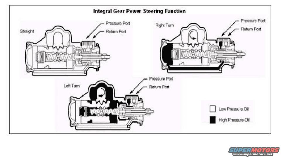
Integral Gear Power Steering Fluid Flow Diagram - Ford Bronco Gear Box Schematic
Reference · 1987-1991 BroncoAll 110 schematics















Integral gear power steering function schematic with cutaways showing high/low pressure oil flow during turns.
Part of 1987-1991 Ford Bronco Schematics
This schematic, titled "Integral Gear Power Steering Function," illustrates the hydraulic fluid flow inside an integral power steering gear box under three operating conditions: Straight, Right Turn, and Left Turn. Each of the three cutaway drawings shows the steering gear assembly with two labeled hydraulic connections, the Pressure Port and the Return Port, indicated by arrows. A legend at the lower right distinguishes Low Pressure Oil (shown as white/unshaded areas) from High Pressure Oil (shown as black/shaded areas). In the Straight-ahead view, no areas are shaded high pressure, indicating balanced pressure. In the Right Turn view, high-pressure oil fills one side of the gear housing, and in the Left Turn view, high-pressure oil fills the opposite side and areas around the valve body, demonstrating how the rotary valve directs pressurized fluid to opposite sides of the power piston depending on steering direction. The document contains no year, make, model, part numbers, torque specifications, or fluid capacities, it is purely a functional/hydraulic flow illustration. It was uploaded as reference for a 1990 Ford Bronco, and nothing in the diagram contradicts that application, though the diagram itself is generic and unbranded.
Is this accurate? Sign in to help verify it.
Frequently asked questions
- What does this diagram show?
- It shows the hydraulic function of an integral gear power steering box in three states: Straight, Right Turn, and Left Turn, with fluid flow through the Pressure Port and Return Port.
- How is high pressure oil distinguished from low pressure oil in the diagram?
- A legend indicates Low Pressure Oil as white (unshaded) areas and High Pressure Oil as black (shaded) areas in the cutaway views.
- What ports are labeled on the steering gear?
- Each cutaway view labels two ports: the Pressure Port and the Return Port.
- What happens to the oil pressure when the wheel is turned?
- During a right or left turn, high pressure oil (shown in black) fills one side of the gear housing, on opposite sides depending on turn direction; when steering straight, the diagram shows only low pressure oil.






No comments yet.