1990 Ford Bronco 5.8L Thermactor Air Pump & Bypass Valve Location Diagram

Reference · 1987-1991 BroncoAll 111 schematics
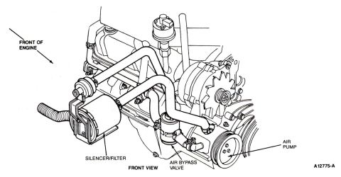
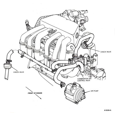
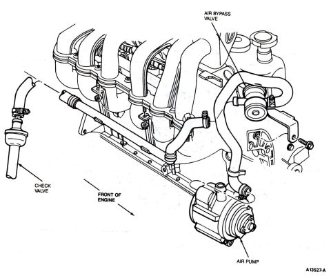
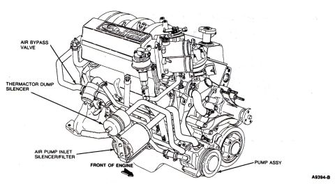
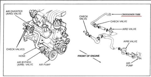
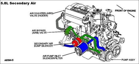









Secondary air schematic showing the air bypass valve, thermactor dump silencer, air pump inlet filter and pump assembly on the engine.
Part of 1987-1991 Ford Bronco Schematics
This document is a Ford factory-style line drawing (figure reference A9394-B) showing the Thermactor secondary air injection system components on a Ford V8 engine equipped with Electronic Fuel Injection, as indicated by the 'Ford Electronic Fuel Injection' lettering on the upper intake manifold. The illustration is a front three-quarter perspective view of the engine with an arrow labeled 'FRONT OF ENGINE' establishing orientation. Callout arrows identify four key emissions components and their mounting locations: the Air Bypass Valve (mounted high on the driver's side near the intake), the Thermactor Dump Silencer (located low on the front driver's side of the engine), the Air Pump Inlet Silencer/Filter (mounted at the lower front of the engine ahead of the air pump), and the Pump Assembly (the belt-driven Thermactor air pump with pulley at the lower passenger side front of the engine). The drawing contains no text tables, torque values, wire colors, or part numbers other than the figure number, and it does not state a model year or specific engine displacement. It was uploaded as part of a set of 1990 Ford Bronco emissions documents and is claimed to apply to the 5.8L engine.
Is this accurate? Sign in to help verify it.
Frequently asked questions
- Where is the Thermactor air pump located on this Ford EFI engine?
- The diagram shows the pump assembly (labeled 'PUMP ASSY') mounted low at the front of the engine on the passenger side, driven by a pulley, with the air pump inlet silencer/filter mounted just ahead of it.
- What components are identified in this diagram?
- The drawing labels the Air Bypass Valve, Thermactor Dump Silencer, Air Pump Inlet Silencer/Filter, and the Pump Assembly, plus an arrow indicating the front of the engine.
- Where is the Thermactor dump silencer located?
- According to the callout arrow, the Thermactor dump silencer is located low on the front driver's side of the engine, above the air pump inlet silencer/filter.
- Does this diagram apply to a fuel-injected engine?
- Yes: the upper intake plenum in the drawing is marked 'Ford Electronic Fuel Injection,' indicating an EFI engine.
- What is the figure reference number of this diagram?
- The figure is labeled A9394-B in the lower right corner.






No comments yet.