Home/
Registry/
Ford/
Bronco/
1992-1996/
“Eddie Bauer”/
Photo
supermotors.net/registry/media/1023939
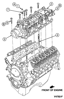
1994 Ford Bronco V8 Intake Manifold Installation Exploded Diagram (V4792-F)
Reference · 1992-1996 BroncoAll 169 exploded parts diagrams
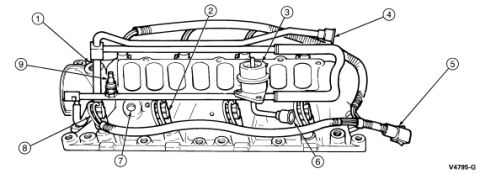
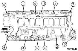
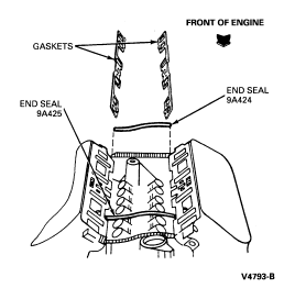
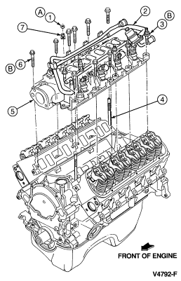
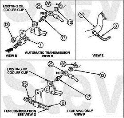
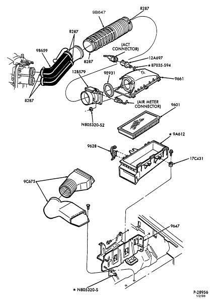
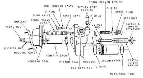
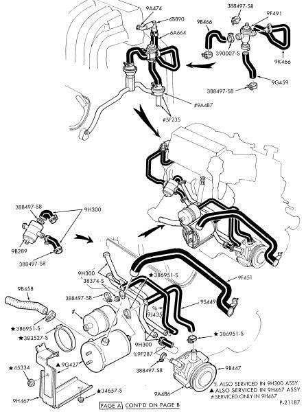


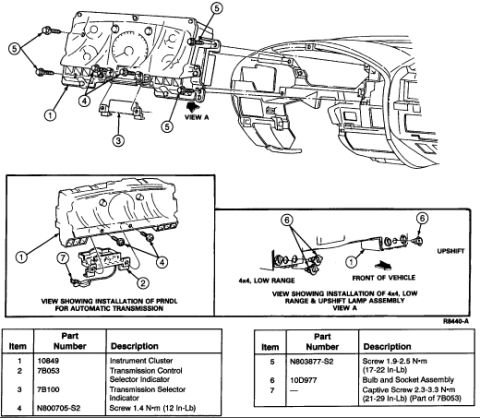
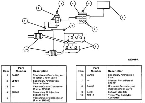










Exploded parts diagram of the engine showing intake manifold and cylinder head assembly with numbered callouts.
Part of 1992-1996 Ford Bronco Exploded Parts Diagrams
This document is an exploded-view line drawing showing the installation of the upper and lower intake manifold assembly onto a V8 engine, uploaded as reference material for a 1994 Ford Bronco. The illustration depicts the engine block with valvetrain (rocker arms and pushrods visible on both cylinder banks), the lower intake manifold, the upper intake/throttle body plenum, and the associated mounting bolts and studs shown lifted above their installed positions. Numbered callouts (1, 3, 4, 5, 6, 7) and lettered callouts (A and B) identify individual fasteners and components, though no legend or key defining these callouts appears on this page, it is presumably on an accompanying page in the same album (which includes intake gasket diagrams and a lower intake torque sequence). A directional arrow labeled 'FRONT OF ENGINE' establishes orientation, and the figure carries the Ford illustration reference number V4792-F. A reader can learn the relative positions and stacking order of the intake components and fasteners during assembly, and the orientation of the assembly relative to the front of the engine, but must consult companion pages for part names, torque values, and tightening sequences.
Is this accurate? Sign in to help verify it.
Frequently asked questions
- What does this diagram show?
- An exploded view of the intake manifold assembly (lower intake and upper intake/plenum) and its fasteners being installed on a V8 engine, with callouts A, B, and 1, 3, 4, 5, 6, 7 identifying components.
- Does this diagram include torque specifications or a bolt tightening sequence?
- No. This page shows only the exploded assembly view with callout numbers; no torque values or sequence numbers appear. The same album contains a separate 'lower intake torque sequence' document.
- How is the engine oriented in the diagram?
- An arrow labeled 'FRONT OF ENGINE' at the bottom right indicates the front of the engine points to the right side of the illustration.
- What is the figure reference number on this diagram?
- The illustration is labeled V4792-F in the bottom right corner.






No comments yet.