Home/
Registry/
Ford/
Bronco/
1992-1996/
“Daddy's Bad Ass Bronco”/
Photo
supermotors.net/registry/media/1032551
1995 Ford Thunderbird EGR Position Sensor (DPFE) Simulator Circuit Schematic
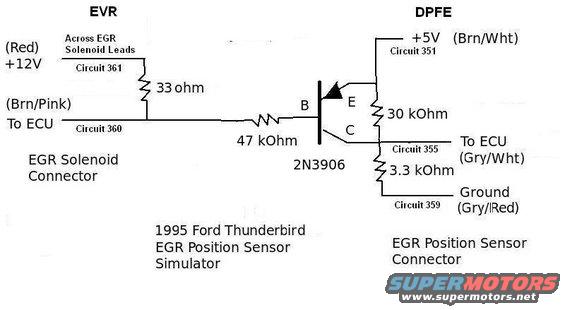
Electronic circuit schematic of an EGR position sensor simulator using a 2N3906 transistor and resistors with circuit numbers and wire colors.
Part of 1992-1996 Ford Bronco Schematics
This document is a hand-drawn electrical schematic for a "1995 Ford Thunderbird EGR Position Sensor Simulator." It shows a small circuit built around a 2N3906 PNP transistor that mimics the DPFE (Differential Pressure Feedback EGR) position sensor signal using the EVR (EGR Vacuum Regulator) solenoid drive signal. On the EVR side, the EGR solenoid connector provides +12V on a Red wire (Circuit 361) and the Brn/Pink ECU control wire (Circuit 360); a 33 ohm resistor is placed across the EGR solenoid leads. Circuit 360 feeds the transistor base through a 47 kOhm resistor. On the DPFE side, the EGR position sensor connector supplies +5V on a Brn/Wht wire (Circuit 351) to the transistor emitter, with a 30 kOhm resistor to the collector node. The collector output drives Circuit 355 (Gry/Wht) back to the ECU as the simulated sensor signal, with a 3.3 kOhm resistor to ground on Circuit 359 (Gry/Red). A reader can learn the wire colors, Ford circuit numbers, resistor values, and transistor type needed to build this EGR position sensor simulator circuit.
This document covers 1995, which may differ from this 1996 Ford Bronco.
Is this accurate? Sign in to help verify it.
Frequently asked questions
- What transistor is used in this EGR position sensor simulator?
- A 2N3906 transistor, with its base (B) fed through a 47 kOhm resistor, emitter (E) to +5V (Circuit 351), and collector (C) driving the ECU signal on Circuit 355.
- What resistor values does the simulator circuit use?
- A 33 ohm resistor across the EGR solenoid leads (Circuits 361/360), a 47 kOhm resistor to the transistor base, a 30 kOhm resistor from +5V to the collector node, and a 3.3 kOhm resistor from the output to ground.
- What are the wire colors and circuit numbers at the EGR position sensor (DPFE) connector?
- +5V is Brn/Wht (Circuit 351), the signal to the ECU is Gry/Wht (Circuit 355), and ground is Gry/Red (Circuit 359).
- What wires are at the EGR solenoid (EVR) connector?
- A Red +12V wire (Circuit 361) and a Brn/Pink wire to the ECU (Circuit 360), with a 33 ohm resistor placed across the EGR solenoid leads.
- What vehicle does this schematic apply to?
- The drawing is labeled '1995 Ford Thunderbird EGR Position Sensor Simulator.'
Comments
More from this build








No comments yet.