Home/
Registry/
Ford/
Bronco/
1992-1996/
1996 Ford Bronco/
Photo
supermotors.net/registry/media/1106852
1996 Ford Bronco EVTM 151-1 Component Location Views - 5.0L/5.8L Engine Bay
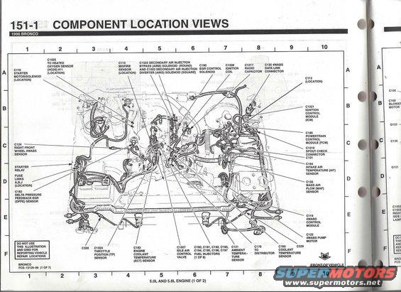
1996 Bronco component location view (151-1) for 5.0L and 5.8L engines mapping PCM, MAF, IAT, DPFE, EGR, oxygen sensor, ICM and 4WABS connectors on a grid.
Part of 1992-1996 Ford Bronco Schematics
This is a scanned page (Section 151-1, "Component Location Views") from the 1996 Ford Bronco Electrical and Vacuum Troubleshooting Manual (EVTM). It shows an engine compartment illustration for the 5.0L and 5.8L engines (sheet 1 of 2), overlaid with a locator grid (columns 1-10, rows A-F). Callout arrows identify the physical locations of electrical components and connectors, including the starter motor/solenoid (C116), starter relay, fuse links A, B, J, heated oxygen sensor connector C1025, misfire sensor C115, secondary air injection AIRB (C1022) and AIRD (C1023) solenoids, EGR control solenoid C180, ignition coil C1008, radio capacitor C1017, 4WABS data link connector C120, ignition control module C1021, powertrain control module C185, SPOUT check connector C1019/C101, IAT sensor C164, MAF sensor C130, right front wheel 4WABS sensor C124, DPFE sensor C182, 4WABS control module C119, 4WABS pump motor C122, throttle position sensor C1024, ECT sensor C183, idle air control valve C1007, fuel injectors C190-C197, ambient temperature sensor C131, distributor connector C178, coolant temperature sensor C150, plus C329 and C330. The drawing is labeled FCS-12129-96 (1 of 7) and notes it should not be used for reporting vehicle repair locations. It helps a reader physically locate engine bay sensors, modules, and connectors when diagnosing 1996 Bronco electrical issues.
Is this accurate? Sign in to help verify it.
Frequently asked questions
- Where is the PCM (Powertrain Control Module) shown on a 1996 Bronco?
- The diagram identifies the powertrain control module as connector C185, located on the passenger (right) side of the engine compartment near the firewall in the illustration.
- What connector numbers are the fuel injectors on the 1996 Bronco 5.0L/5.8L?
- The fuel injectors are connectors C190, C191, C192, C193, C194, C195, C196, and C197 (1 of 8 shown).
- Where are fuse links A, B, and J located?
- The diagram places fuse links A, B, and J on the driver's side of the engine compartment near the starter relay, shown in the left/lower-left area of the illustration.
- Which engines does this component location view cover?
- It is labeled '5.0L AND 5.8L ENGINE (1 OF 2)' for the 1996 Bronco.
- What are the 4WABS component locations shown?
- The diagram shows the C120 4WABS data link connector, C124 right front wheel 4WABS sensor, C119 4WABS control module, and C122 4WABS pump motor.
Comments
More from this build












No comments yet.