Home/
Registry/
Ford/
Bronco/
1992-1996/
“Eddie Bauer”/
Photo
supermotors.net/registry/media/1023942
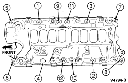
1994 Ford Bronco Lower Intake Manifold Bolt Torque Sequence Diagram (V4794-B)
Reference · 1992-1996 BroncoAll 169 exploded parts diagrams
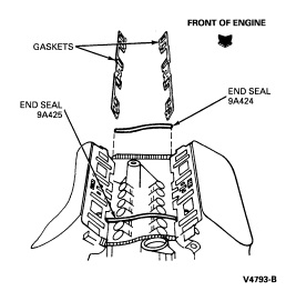
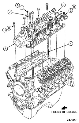
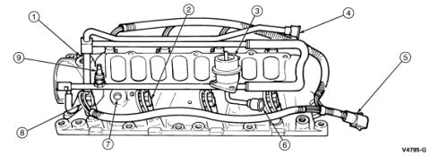
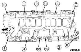
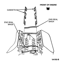
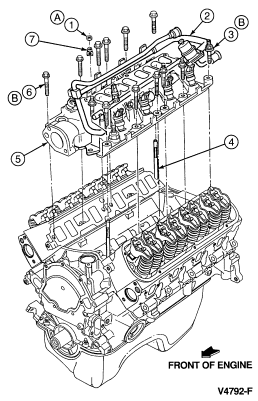
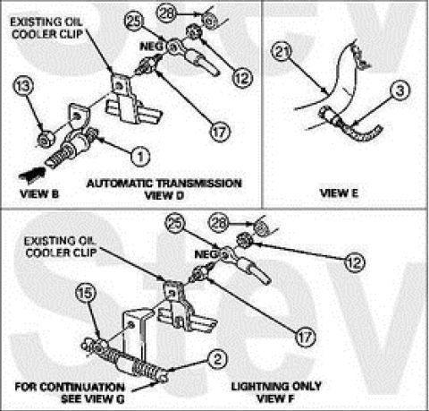
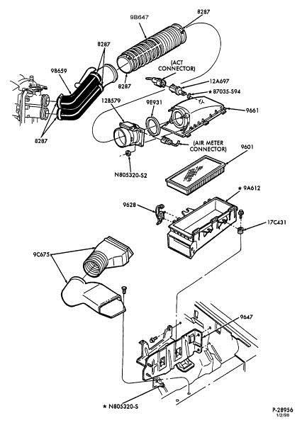


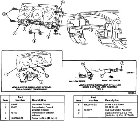
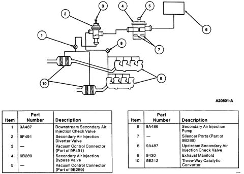










Exploded parts diagram of the intake manifold showing the numbered bolt tightening sequence.
Part of 1992-1996 Ford Bronco Exploded Parts Diagrams
This document is a line-art diagram showing the bolt tightening (torque) sequence for a lower intake manifold, identified by Ford figure number V4794-B. The illustration depicts the manifold viewed from above, with an arrow labeled 'FRONT' indicating the front of the engine (left side of the drawing). Twelve numbered callouts (1 through 12) point to the manifold bolt locations, indicating the order in which the bolts should be tightened. Along the top edge of the manifold, the sequence positions shown left to right are 5, 1, 9, 11, 3, and 7; along the bottom edge, left to right, they are 6, 4, 12, 10, 2, and 8. The pattern works from the center bolts outward in an alternating crisscross fashion, which is typical for intake manifold installation to ensure even gasket clamping. The diagram contains no torque values, part numbers (other than the figure ID), year/model applicability, or text instructions, it is purely a visual sequence reference. It was uploaded as part of an album of engine and intake installation documents for a 1994 Ford Bronco, suggesting it applies to that vehicle's V8 engine intake installation procedure, though the document itself does not state applicability.
Is this accurate? Sign in to help verify it.
Frequently asked questions
- What is the lower intake manifold bolt tightening sequence shown in this diagram?
- The diagram numbers the 12 manifold bolts in tightening order. Along the top edge (left to right) the positions are 5, 1, 9, 11, 3, 7; along the bottom edge (left to right) they are 6, 4, 12, 10, 2, 8. Bolts are tightened starting near the center and working outward in an alternating pattern.
- How many bolts are in the intake manifold torque sequence?
- Twelve bolts are numbered in the sequence, six along each side of the manifold.
- Which end of the diagram is the front of the engine?
- An arrow labeled 'FRONT' points to the left side of the illustration, indicating the front of the engine is at the left.
- Does this diagram list torque values for the intake bolts?
- No. The diagram only shows the bolt tightening order (1 through 12); no torque specifications are printed on it.






No comments yet.