Home/
Registry/
Hyundai/
Genesis Coupe/
2010-2016/
“Coupe”/
Photo
supermotors.net/registry/media/1030561
2010 Hyundai Genesis Coupe A/C & Blower Control Wiring Diagram SD971-9 (Manual)

Reference · 2010-2016 Genesis CoupeAll 79 wiring diagrams
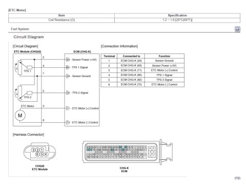
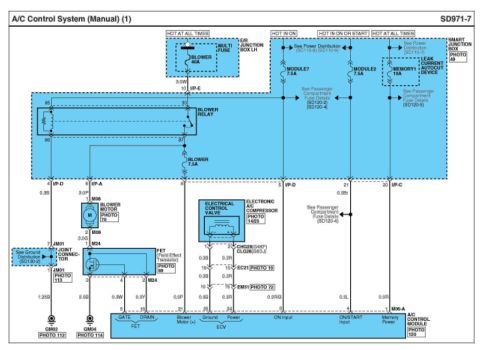
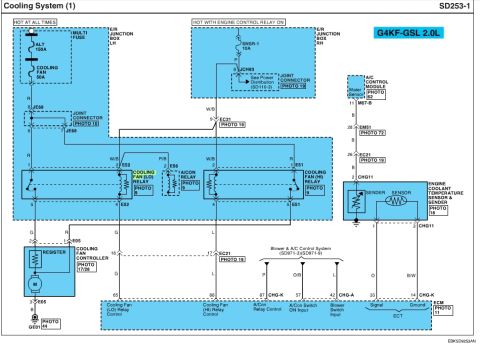
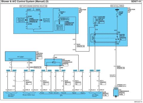
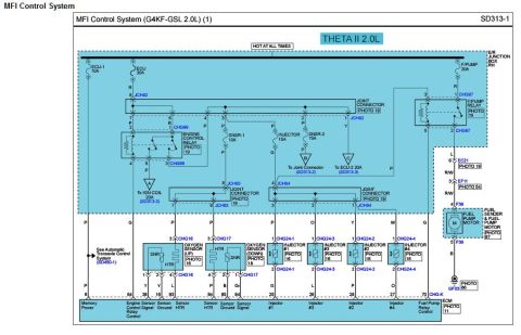
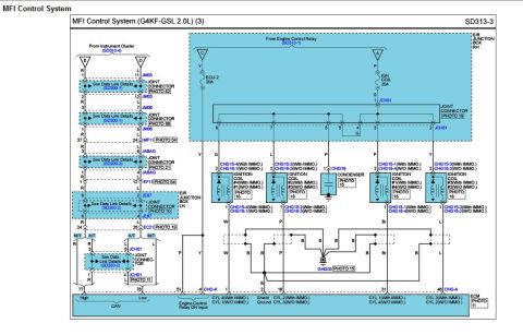
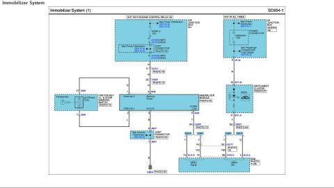









Electrical wiring diagram of the manual blower and A/C control system showing relays, connectors and color-coded circuits.
Part of 2010-2016 Hyundai Genesis Coupe Wiring Diagrams
This is page 3 of the 'Blower & A/C Control System (Manual)' wiring diagram, page number SD971-9, from a Hyundai factory-style service manual (drawing code EBKSD9971IN). It shows power feeds for the manual A/C system: a circuit hot with the engine control relay on, passing through joint connectors JCH82 and JCH83(G4KF)/JCL83(G6DA) in the E/R junction box RH, protected by the SNSR-1 10A fuse; and a hot-at-all-times feed through the A/CON COMP 10A fuse in the E/R junction box LH. The diagram covers the cooling fan (LO) relay (connector E52), the A/CON relay (connector E56), the A/C control module (connectors M06/EM51), the A/C pressure transducer (connector E02, three pins labeled Power, Ground, Signal to the ECM as APT), and the A/C compressor clutch (connector CHG28 for G4KF engine / CLG28 for G6DA engine). Wire colors shown include Y, L, O, G, P, W/B, P/B, O/B, and W(G4KF)/O(G6DA). ECM pin assignments are listed for A/C switch ON input, blower switch input, pressure transducer power/ground/signal, and A/C relay control, with separate ELG-A/CHG-A/CHG-K connector variants for the G4KF (2.0L) and G6DA (3.8L) engines. Photo references (3, 9, 14/25, 19, 72, 88, 11/36) locate each component.
Is this accurate? Sign in to help verify it.
Frequently asked questions
- What fuse powers the A/C compressor circuit on this diagram?
- The A/CON COMP 10A fuse in the E/R junction box LH (hot at all times) feeds the A/CON relay and compressor circuit; the SNSR-1 10A fuse (hot with engine control relay on) feeds the sensor/joint connector side.
- Which relay controls the A/C compressor?
- The A/CON relay (connector E56, photo 9) in the E/R junction box, with the cooling fan (LO) relay at connector E52 also shown. The ECM provides A/C relay control on the bottom of the diagram.
- What connector is the A/C pressure transducer on and what are its pins?
- The A/C pressure transducer uses connector E02 (photo 3) with three pins routed to the ECM as Power, Ground, and Signal (labeled APT).
- Does this diagram cover both engines?
- Yes: it shows G4KF and G6DA variants, including joint connectors JCH83(G4KF)/JCL83(G6DA), compressor connectors CHG28(G4KF)/CLG28(G6DA), and wire color W(G4KF)/O(G6DA).
- Where does the A/C control module connect?
- The A/C control module (photo 88) shows an A/C (High) select/output section with pins 21/22 at connector M06 and 15/16 at connector EM51 (photo 72), sending Y and L wires to the ECM as A/C switch ON input and blower switch input.

No comments yet.