Home/
Registry/
Hyundai/
Genesis Coupe/
2010-2016/
“Coupe”/
Photo
supermotors.net/registry/media/888277
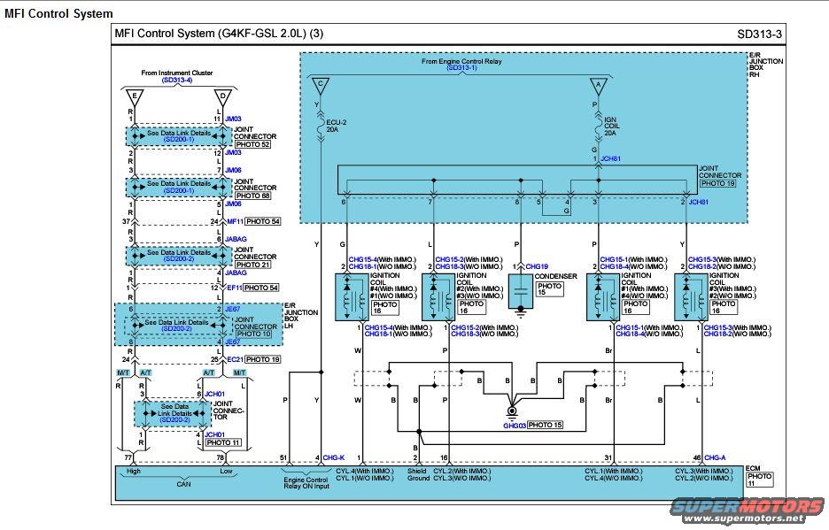
Hyundai Genesis Coupe 2.0T Ignition Coil Wiring Diagram SD313-3 (G4KF 2.0L MFI)
Reference · 2010-2016 Genesis CoupeAll 79 wiring diagrams
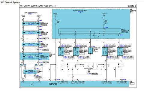









Electrical wiring diagram of an MFI engine control system showing connectors, relays, ignition coils, and color-coded wires.
Part of 2010-2016 Hyundai Genesis Coupe Wiring Diagrams
This is page 3 of the MFI (Multiport Fuel Injection) Control System wiring diagram, sheet SD313-3, for the Hyundai G4KF-GSL 2.0L engine (Genesis Coupe 2.0T). It shows the ignition coil circuit: power comes from the Engine Control Relay (SD313-1) through the ECU-2 20A and IGN COIL 20A fuses in the RH engine-room junction box, then through joint connector JCH61 to four ignition coils. Each coil connector is identified for both immobilizer-equipped and non-immobilizer vehicles (CHG15-1 through CHG15-4 With IMMO.; CHG18-1 through CHG18-4 W/O IMMO.), with cylinder assignments differing between the two configurations. A condenser (CHG19) is shown on the circuit with its ground. Coil control signals return to ECM pins 4, 16, 31, and 46, with a shield ground on pin 3 joining chassis ground GHG03. The left side shows the CAN data link path from the instrument cluster through joint connectors JM03, JM06, JABAG, JE67, EC21, and JCH01 (M/T vs A/T routing) to ECM pins 77 (CAN High, red wire) and 78 (CAN Low, blue wire). Wire colors (Y, G, L, P, Br, W, B, R) and photo/connector location references are given throughout.
Is this accurate? Sign in to help verify it.
Frequently asked questions
- Which fuses power the ignition coils on the G4KF 2.0L Genesis Coupe?
- Power comes from the Engine Control Relay (SD313-1) through the ECU-2 20A fuse and the IGN COIL 20A fuse in the E/R junction box (RH), then through joint connector JCH61 to the coils.
- Which ECM pins control the ignition coils?
- ECM pin 4 controls CYL.4 (With IMMO.)/CYL.1 (W/O IMMO.), pin 16 controls CYL.2/CYL.3, pin 31 controls CYL.1/CYL.4, and pin 46 controls CYL.3/CYL.2. Pin 3 is the shield ground.
- What are the ignition coil connector numbers?
- With immobilizer: CHG15-1 through CHG15-4. Without immobilizer: CHG18-1 through CHG18-4. The cylinder assignments swap between the two configurations. The condenser connector is CHG19.
- Which ECM pins carry the CAN bus?
- Pin 77 is CAN High (R wire) and pin 78 is CAN Low (L wire), routed from the instrument cluster through joint connectors JM03, JM06, JABAG, JE67, EC21 and JCH01 (with separate M/T and A/T routing).
- Where does the ignition coil shield ground connect?
- The shield/ground wires (B) join at ground point GHG03 (PHOTO 15) and connect to ECM pin 3 (Shield Ground).

No comments yet.