Home/
Registry/
Hyundai/
Genesis Coupe/
2010-2016/
“Coupe”/
Photo
supermotors.net/registry/media/871005
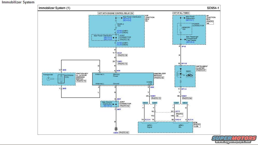
Hyundai Genesis Coupe Immobilizer System Wiring Diagram SD954-1 (2010)
Reference · 2010-2016 Genesis CoupeAll 79 wiring diagrams
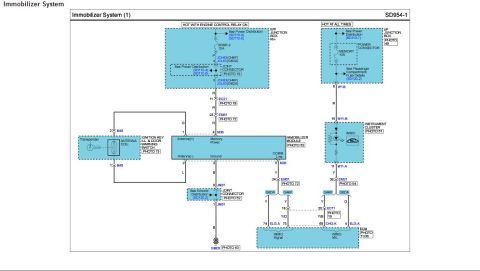









Electrical wiring diagram of an immobilizer system showing connectors, fuses, transponder coil, and control modules.
Part of 2010-2016 Hyundai Genesis Coupe Wiring Diagrams
This document is page SD954-1, "Immobilizer System (1)," a factory wiring diagram for the vehicle immobilizer (anti-theft) system. It shows two power feeds: the SNSR-2 15A fuse in the E/R (engine room) junction box RH, hot with the engine control relay on, and the MEMORY 10A fuse in the I/P junction box, hot at all times. Power routes through joint connectors JCH83 (G4KF engine) or JCL83 (G6DA engine) and connectors EC21, EM61 to the immobilizer module (connector M36), which contains Antenna(+), Antenna(-), Memory Power, Ground, and COMM Line circuits. The antenna coil around the ignition key transponder connects via connector M43 through the ignition key illumination & door warning switch. Grounding is through joint connector JM01 to ground point GM03. The COMM line runs from the immobilizer module through EM61 and EM21 to the ECM (connectors ELG-A and CHG-K) carrying IMMO. Signal and IMMO. MIL circuits, and to the instrument cluster (M11-A/M11-B) for the IMMO indicator. Wire colors shown include R, G, L, B, Y, Y/O, Y/B, with engine-specific color variations for G4KF vs G6DA engines. Photo references and cross-references to power distribution pages (SD110-4/6/7, SD120-2, SD130-2) are included.
Is this accurate? Sign in to help verify it.
Frequently asked questions
- What fuses power the immobilizer system?
- Two fuses: the SNSR-2 15A fuse in the E/R junction box RH (hot with engine control relay on) and the MEMORY 10A fuse in the I/P junction box (hot at all times).
- What circuits connect to the immobilizer module?
- The immobilizer module (connector M36) has Antenna(+), Antenna(-), Memory Power, Ground, and a COMM Line that connects to the ECM and the instrument cluster IMMO indicator.
- Where does the immobilizer system ground?
- The module's ground pin routes through joint connector JM01 (pins 9 and 1) with a black (B) wire to ground point GM03.
- What ECM pins are used for the immobilizer?
- The ECM receives the IMMO. Signal on connector ELG-A pins 74/75 and the IMMO. MIL on CHG-K pin 69 and ELG-A pin 4, with wire colors varying by engine (G4KF vs G6DA).
- Which engines does this diagram distinguish between?
- The diagram shows engine-specific joint connectors and wire colors for the G4KF and G6DA engines (e.g., JCH83 for G4KF, JCL83 for G6DA).

No comments yet.