Home/
Registry/
Hyundai/
Genesis Coupe/
2010-2016/
“Coupe”/
Photo
supermotors.net/registry/media/1042345
Hyundai Genesis Coupe ETC Motor Circuit Diagram & ECM CHG-K Pinout

Reference · 2010-2016 Genesis CoupeAll 79 wiring diagrams
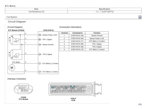
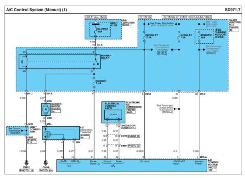
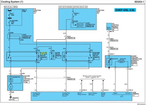
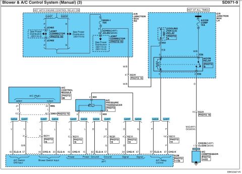
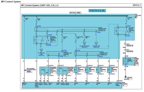








Electronic throttle control (ETC) circuit diagram showing TPS1/TPS2 and ETC motor wiring to the ECM CHG-K connector, with 6-terminal function table and CHG22 harness pinout; motor coil 1.2-1.8 ohm.
Part of 2010-2016 Hyundai Genesis Coupe Wiring Diagrams
This service-manual page covers the Electronic Throttle Control (ETC) system circuit for the fuel system. It begins with an ETC Motor specification table listing coil resistance of 1.2-1.8 Ω at 20°C (68°F). The circuit diagram shows the ETC Module (connector CHG22) wired to the ECM (connector CHG-K): terminal 1 to ECM pin 59 (Sensor Ground), terminal 2 to pin 63 (Sensor Power +5V), terminal 3 to pin 71 (ETC Motor [+] Control), terminal 4 to pin 80 (TPS 1 Signal), terminal 5 to pin 82 (TPS 2 Signal), and terminal 6 to pin 72 (ETC Motor [-] Control). A connection information table repeats these terminal assignments. The harness connector section illustrates the 6-pin CHG22 ETC Module connector face (pins 3-2-1 over 6-5-4) and the 94-pin CHG-K ECM connector with the full numbered pin layout, highlighting the six pins used by the ETC circuit. A reader can use this page to identify ETC/throttle position sensor wiring, test coil resistance of the throttle motor, and locate the correct ECM pins for continuity or signal testing. The uploader labels it as applying to a 2014 Hyundai Genesis Coupe.
Is this accurate? Sign in to help verify it.
Frequently asked questions
- What is the coil resistance specification for the ETC motor?
- 1.2 ~ 1.8 Ω at 20°C (68°F).
- Which ECM pins connect to the ETC module?
- ECM CHG-K pin 59 (Sensor Ground), 63 (Sensor Power +5V), 71 (ETC Motor [+] Control), 80 (TPS 1 Signal), 82 (TPS 2 Signal), and 72 (ETC Motor [-] Control).
- Which ETC module terminals carry the TPS signals?
- Terminal 4 is TPS 1 Signal (to ECM pin 80) and terminal 5 is TPS 2 Signal (to ECM pin 82).
- What connectors are shown in the harness connector section?
- CHG22, the 6-pin ETC Module connector, and CHG-K, the 94-pin ECM connector with numbered pin layout.
- Which ETC module pins control the throttle motor?
- Terminal 3 is ETC Motor [+] Control (ECM pin 71) and terminal 6 is ETC Motor [-] Control (ECM pin 72).

No comments yet.