Home/
Registry/
Hyundai/
Genesis Coupe/
2010-2016/
“Coupe”/
Photo
supermotors.net/registry/media/888278
Hyundai Genesis Coupe 2.0L Theta II MFI Wiring Diagram SD313-1 - O2 & Injectors
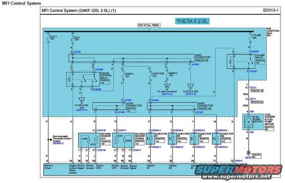
Electrical wiring diagram of a Theta II 2.0L MFI control system showing relays, injectors, sensors, and color-coded wires.
Part of 2010-2016 Hyundai Genesis Coupe Wiring Diagrams
This is page SD313-1 of the MFI (Multiport Fuel Injection) Control System wiring diagram for a Hyundai with the G4KF-GSL Theta II 2.0L engine, consistent with the 2010 Genesis Coupe 2.0T. The diagram shows the hot-at-all-times power distribution from the engine room junction box (RH): the ECU-1 10A and ECU 30A fuses feeding the Engine Control Relay (connector CHG99), the SNSR-1 10A, INJECTOR 15A, and SNSR-2 15A fuses, and the F/PUMP 20A fuse feeding the Fuel Pump Relay (CHG97). It traces the fuel pump circuit through connectors EC21, EF11, and F39 to the fuel sender/pump motor and ground GF03. Component circuits include the upstream oxygen sensor (CHG16), downstream oxygen sensor (CHG17), and injectors #1-#4 (CHG24-1 through CHG24-4), each with pin numbers and wire colors. All signals terminate at the ECM (connector CHG-K) with pin assignments for memory power (64), engine control relay control (38), O2 sensor signals/grounds/heaters, injector drivers (25, 26, 27, 24), and fuel pump relay control (70). Cross-references point to SD313-2, SD313-3, SD450-1 (automatic transaxle), and component photo callouts (Photos 11, 16, 18, 19, 54, 87, 88).
Is this accurate? Sign in to help verify it.
Frequently asked questions
- What engine does this MFI wiring diagram cover?
- The G4KF-GSL 2.0L Theta II engine, as stated in the title 'MFI Control System (G4KF-GSL 2.0L) (1)', diagram SD313-1.
- What fuses power the MFI control system?
- From the E/R junction box (RH): ECU-1 10A, ECU 30A, SNSR-1 10A, INJECTOR 15A, SNSR-2 15A, and F/PUMP 20A. References also point to IGN COIL 20A (SD313-3) and ECU-2 20A (SD313-3).
- Which ECM pins control the fuel injectors?
- ECM connector CHG-K: pin 25 (G wire) Injector #1, pin 26 (L) Injector #3, pin 27 (P) Injector #2, and pin 24 (O) Injector #4.
- Which ECM pin controls the fuel pump relay?
- Pin 70 (G wire) on ECM connector CHG-K is the Fuel Pump Relay Control; the relay itself is connector CHG97 fed by the F/PUMP 20A fuse.
- What are the oxygen sensor connector numbers?
- The upstream oxygen sensor uses connector CHG16 and the downstream oxygen sensor uses connector CHG17, both shown with heater (HTR) and sensor (SNR) elements.
Comments
More from this build









No comments yet.