Home/
Registry/
Ford/
Bronco/
1992-1996/
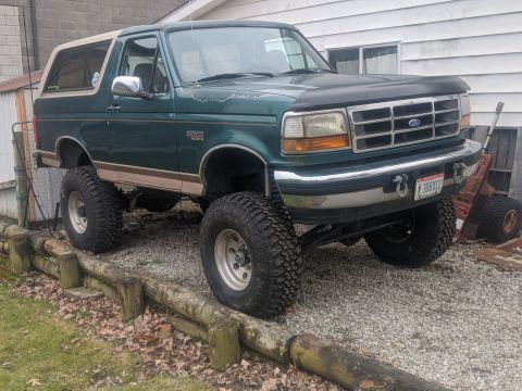
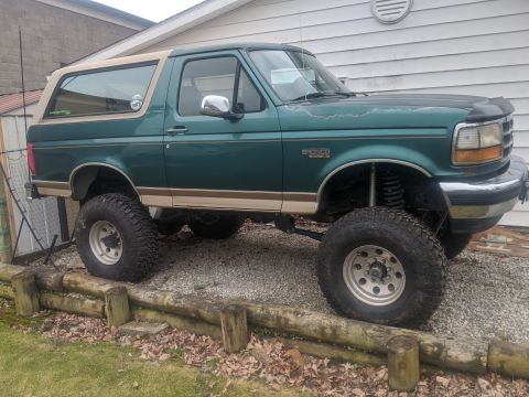
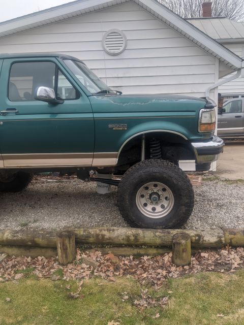
1996 Ford Bronco/
Photo
supermotors.net/registry/media/1008561
Driveshaft & Pinion Angle CAD Diagram - 14° Pinion, 25° Driveshaft (Ford Bronco)
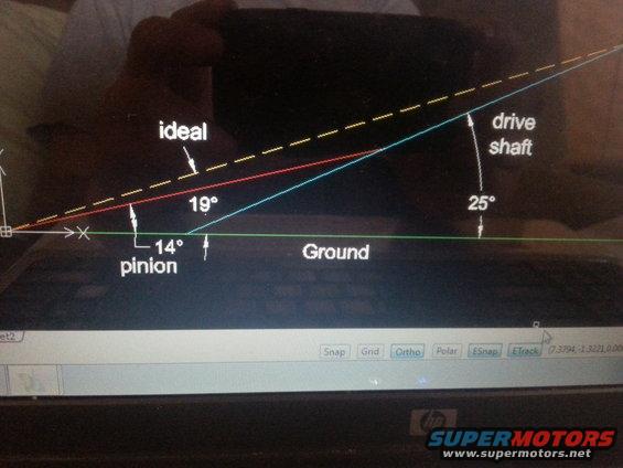
Driveline geometry schematic comparing ideal versus actual pinion and driveshaft angles relative to ground.
This is a photograph of a laptop screen displaying a CAD drawing (apparently AutoCAD, based on the visible Snap/Grid/Ortho/Polar/ESnap/ETrack status bar and coordinate readout) that diagrams vehicle driveline geometry angles relative to the ground. A green horizontal line represents the Ground. A dashed yellow line labeled 'ideal' rises from the origin. A red line at 19° from the ground represents an intermediate angle, and a separate label indicates a 14° pinion angle measured near the origin. A blue line labeled 'drive shaft' rises at 25° from the ground plane. The diagram appears to be a planning/measurement sketch for driveshaft and pinion angle alignment, likely for setting up a lifted or modified suspension so that the pinion angle, driveshaft angle, and ideal alignment line can be compared. The reader can learn the measured/planned angles in this specific setup: pinion at 14°, an intermediate 19° line, driveshaft at 25°, and the 'ideal' reference line. No vehicle year, make, model, or part numbers appear in the image itself; the attribution to a 1996 Ford Bronco comes from the uploader's gallery, not from the drawing.
Is this accurate? Sign in to help verify it.
Frequently asked questions
- What driveshaft angle is shown in this diagram?
- The drive shaft line is shown at 25° relative to the ground line.
- What pinion angle is indicated?
- The pinion angle is labeled as 14° from the ground reference.
- What does the 19° measurement represent?
- A red line in the diagram is dimensioned at 19°, lying between the 14° pinion line and the dashed 'ideal' line; the diagram does not explicitly name what the 19° line represents.
- What software was used to make this drawing?
- The visible status bar with Snap, Grid, Ortho, Polar, ESnap, and ETrack buttons and a coordinate readout (7.3794, -1.3221, 0.00...) indicates a CAD program such as AutoCAD.
Comments
More from this build






No comments yet.