Home/
Registry/
Ford/
Bronco/
1992-1996/
1996 Ford Bronco/
Photo
supermotors.net/registry/media/1010672
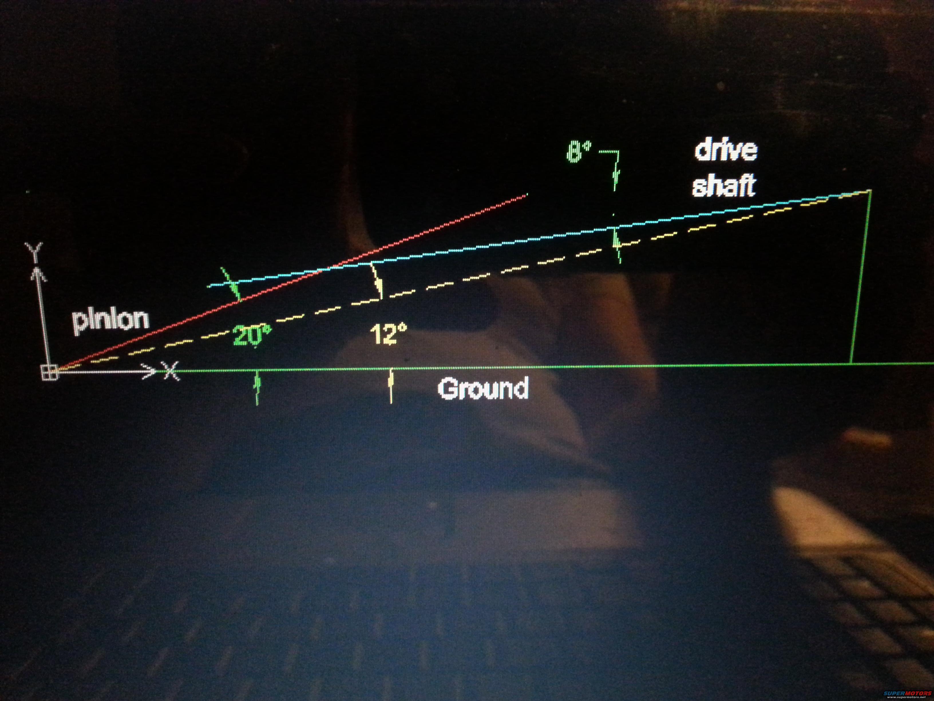
Driveshaft & Pinion Angle Diagram - 20°/12° Ground Angles, 8° U-Joint Angle
Reference · 1992-1996 BroncoAll 95 schematics



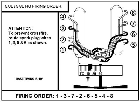
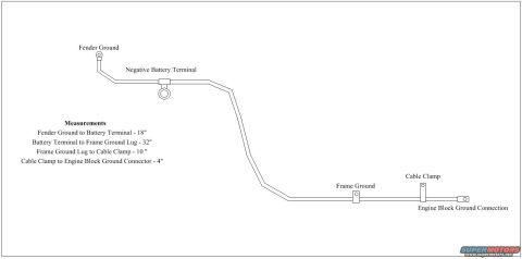
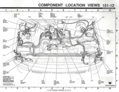
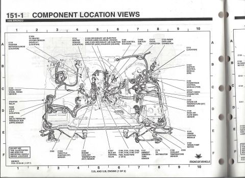








Driveline angle schematic showing pinion and driveshaft angles relative to ground measured in CAD.
Part of 1992-1996 Ford Bronco Schematics
This document is a photograph of a computer screen displaying a CAD-style geometry diagram illustrating driveline angles for a vehicle. A horizontal green line is labeled 'Ground,' with a white X-Y coordinate axis at the left origin. Two lines rise from the origin: a red line labeled 'pinion' at 20° from the ground, and a yellow dashed line at 12° from the ground representing the driveshaft centerline (a cyan line runs parallel above it, labeled 'drive shaft'). Near the right side, an 8° angle is marked between the pinion line direction and the driveshaft line, representing the difference between the two angles (20° − 12° = 8°), i.e., the universal-joint operating angle. From this diagram a reader can learn how pinion angle and driveshaft angle relative to the ground are measured, and how their difference produces the working angle at the U-joint. The sketch appears to be a planning/measurement aid, likely for setting up pinion angle during a suspension lift or axle modification on the uploader's vehicle. No part numbers, fuse data, torque specifications, model years, or vehicle identification appear anywhere in the image; it is purely a geometric angle illustration.
Is this accurate? Sign in to help verify it.
Frequently asked questions
- What pinion angle is shown in this diagram?
- The pinion line is drawn at 20° measured up from the ground line.
- What is the driveshaft angle relative to the ground?
- The driveshaft centerline is shown at 12° from the ground line.
- What is the resulting angle between the pinion and the driveshaft?
- An 8° angle is marked between the pinion line and the driveshaft line (the difference between 20° and 12°).
- What reference line are the angles measured from?
- Both the 20° pinion angle and the 12° driveshaft angle are measured from a horizontal line labeled 'Ground.'






No comments yet.