Home/
Registry/
Ford/
Bronco/
1978-1979/
1979 Ford Bronco/
Photo
supermotors.net/registry/media/1032637
1979 Ford Bronco F100-F350 Trailer Wiring Diagram - Trailer Circuitry & Fuses
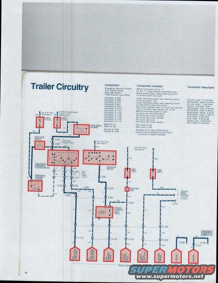
Trailer wiring schematic tying stop light switch, turn signal flasher, emergency warning flasher, and trailer exterior light relay to the customer-installed trailer connector, with component locations.
This document is page 18 of a Ford factory wiring diagram booklet covering the Bronco and F100 through F350 trucks, titled "Trailer Circuitry." It presents the complete trailer towing wiring schematic, including power feeds from Fuse 8 (20 Amps, hot at all times) and Fuse 9 (15 Amps, hot when ignition switch is in Accy. or Run), plus Fuse Link E and Fuse Link A. The diagram traces circuits through the turn signal flasher, stop light switch, turn signal/emergency flasher switch, emergency warning flasher, headlight switch, junction box, trailer exterior light relay, and the customer-installed trailer brake control, down to the customer-installed trailer connector. Trailer connector functions and wire colors are shown: RH turn signal/stop light (gr), LH turn signal/stop light (y/bk), tail running lights (br), trailer battery feed (bk/y), trailer brake stop light (r/bk), electric brakes (bl/bk), and two grounds (bk). A component location legend lists where each component, connector (C-305, C-306, C-713, C-901, C-1001, C-1013, C-1101 through C-1110), splice (S-101, S-102), and ground (G-1003, G-1106) is located on the vehicle, along with connector shapes, colors, and terminal counts. Notes indicate portions apply only with speed control and one ground path is F100-350 only.
Is this accurate? Sign in to help verify it.
Frequently asked questions
- What fuses power the trailer circuits?
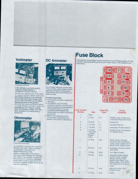
- Fuse 8 (20 Amps, hot at all times) and Fuse 9 (15 Amps, hot when the ignition switch is in Accy. or Run), plus Fuse Link E and Fuse Link A for the trailer battery feed and electric brake circuits.
- What are the wire colors at the trailer connector?
- RH turn signal/stop light = gr, LH turn signal/stop light = y/bk, tail/running lights = br, trailer battery feed = bk/y, trailer brake stop light = r/bk, electric brakes = bl/bk, and grounds = bk. The trailer connector is customer installed.
- Where is the trailer exterior light relay located?
- On the LH fender apron near the dash.
- Where is connector C-1101 located and what does it look like?
- Behind the instrument panel on the LH side; it is rectangular, yellow, with 3 terminals, and connects to the customer-installed trailer brake control.
- Where does ground G-1106 attach?
- Its eyelet must be attached to the rear frame; it is customer or dealer installed.
Comments
More from this build







No comments yet.