Home/
Registry/
Ford/
Bronco/
1978-1979/
1979 Ford Bronco/
Photo
supermotors.net/registry/media/1032640
1979 Ford Bronco F100-F350 Wiring Diagram - Stoplight & Turn Signal Circuit
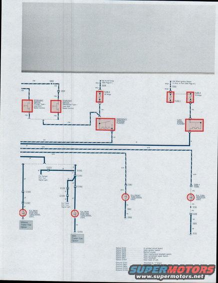
Turn signal / emergency warning / stop light circuit: fuse 9 (15A) and stop light fuse (15A) feed plunger- and mechanical-type stop switches, turn signal switch, and flashers; shows trailer-tow option wiring.
This page (page 21) of a Ford factory-style wiring diagram set for the 1979 Bronco and F100 through F350 trucks covers the stoplight and right-hand turn signal circuits. It shows two stoplight switch variants: a plunger type used without speed control and a mechanical type used with speed control, both fed by red/black (r/bk) wiring through splice S802 and connector C804. Power for the emergency warning flasher comes from a hot-at-all-times feed through Fuse 8 (20 amps), while the turn signal flasher is powered when the ignition switch is in Accy or Run through Fuse 9 (15 amps, with Fuse 11 also shown). Wire colors traced include r/w, w/r, bl, w/bl, gr, gr/w, o/y, bk/y, bk/gr, and bk. The diagram routes to the R.H. rear stop and turn signal light in both 'Without Trailer-Tow Option' and 'With Trailer-Tow Option' configurations, camper and trailer R.H. turn signal light provisions, the R.H. front turn signal light, and the R.H. turn indicator light on the instrument cluster printed circuit. A legend identifies splice locations (S100, S208, S303, S802, S805, S807, S1001) and ground points (G701, G801, G802, G1001, G1002).
Is this accurate? Sign in to help verify it.
Frequently asked questions
- What fuse powers the emergency warning (hazard) flasher on a 1979 Ford Bronco/F-Series?
- Fuse 8, a 20-amp fuse, fed from a hot-at-all-times circuit through splice S208 on black/yellow (bk/y) wires.
- What fuse powers the turn signal flasher?
- Fuse 9, a 15-amp fuse, hot when the ignition switch is in Accy or Run, fed through splice S303 on black/green (bk/gr) wires; Fuse 11 is also shown in this feed. The flasher output to the turn signals is on an orange/yellow (o/y) wire input side.
- What are the two types of stoplight switches shown?
- A plunger type used without speed control and a mechanical type used with speed control; both use red/black (r/bk) wiring.
- Where are the ground points for the turn signal/stop light circuits?
- G701 attached to the 'Y' brace, G801 on the LH radiator support, G802 on the RH radiator support, G1001 eyelet inside body side forward of LH rear lamps, and G1002 eyelet inside body side forward of RH rear lamps.
- What wire color goes to the R.H. front turn signal light?
- Green/white (gr/w) through connector C801, with a black (bk) ground wire through splice S807 to ground G802.
Comments
More from this build







No comments yet.