Home/
Registry/
Hyundai/
Genesis Coupe/
2010-2016/
“Coupe”/
Photo
supermotors.net/registry/media/1054032
Hyundai Genesis Coupe Head Lamps Wiring Diagram SD921-2 - HID & Non-HID

Reference · 2010-2016 Genesis CoupeAll 79 wiring diagrams
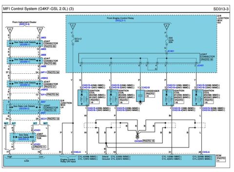
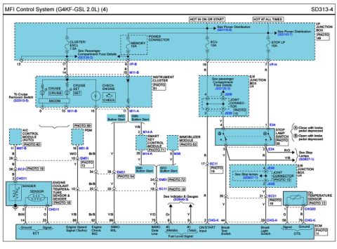
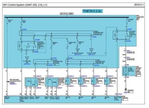
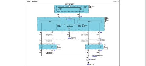
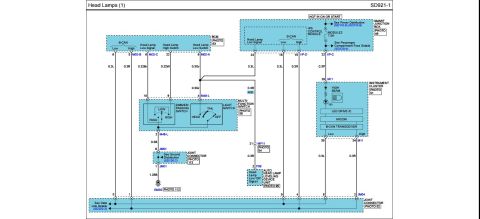
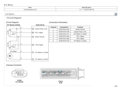
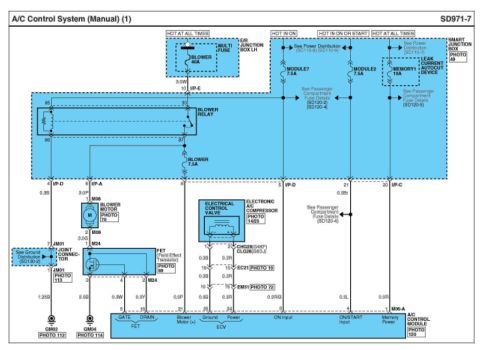
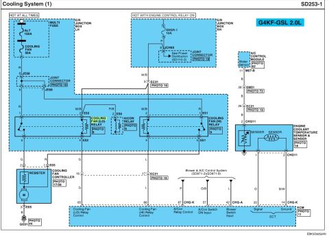








Electrical wiring diagram for the headlamp circuit showing power distribution to high and low beam lamps and the smart junction box.
Part of 2010-2016 Hyundai Genesis Coupe Wiring Diagrams
This document is page SD921-2, "Head Lamps (2)", a headlamp wiring diagram. Power comes from two 60A multi-fuses (B+3 and B+2) in the E/R Junction Box LH, marked "HOT AT ALL TIMES", feeding via 5.0R and 5.0L wires into the Smart Junction Box (pins 1 and 19 I/P-E; see Power Distribution SD110-7). Inside the Smart Junction Box, an IPS Control Module drives ARISU 1 and ARISU 2 outputs for the left and right headlamps, with battery power and HID ground connections. Output wiring differs by equipment: 1.25W (with HID) or 0.5P (without HID) for the left low beam feed, and 1.25P (with HID) or 0.85P (without HID) for the right, plus 0.5R and 0.85R high-beam feeds. The LH headlamp uses connector E95 (pins 2 HI, 1 LO, grounds on pins 6 and 5) and the RH headlamp uses connector E96 (pins 1 LO, 2 HI, grounds on pins 5 and 6). Grounds route through 0.5B/1.25B/0.85B/2.0B wires to joint connector EE11 pin 21 and ground point GE03, with an SJB ground at GE05 (0.3B, pin 23); see Ground Distribution SD130-4. Photo references (PHOTO 1, 2, 5, 44, 49) locate components.
Is this accurate? Sign in to help verify it.
Frequently asked questions
- What fuses power the headlamps in this diagram?
- Two 60A multi-fuses, B+3 and B+2, located in the E/R Junction Box LH on a 'HOT AT ALL TIMES' circuit, feeding the Smart Junction Box via 5.0R and 5.0L wires.
- What controls the headlamp outputs?
- The IPS Control Module inside the Smart Junction Box, using ARISU 1 and ARISU 2 outputs (ARISU 1 Control and ARISU 2 Control, with Battery Power and a Ground (HID) connection).
- Which connectors are used at the headlamps?
- The LH headlamp uses connector E95 (pin 2 HI, pin 1 LO, grounds on pins 6 and 5) and the RH headlamp uses connector E96 (pin 1 LO, pin 2 HI, grounds on pins 5 and 6).
- How do wire sizes differ between HID and non-HID versions?
- The low-beam feeds are 1.25W (with HID) or 0.5P (without HID) on the left, and 1.25P (with HID) or 0.85P (without HID) on the right; the LH ground is 1.25B (with HID) or 0.5B (without HID).
- Where do the headlamp grounds terminate?
- Headlamp grounds join into a 2.0B wire routed through connector EE11 pin 21 to ground point GE03; the Smart Junction Box also grounds at GE05 via a 0.3B wire. See Ground Distribution SD130-4.

No comments yet.