Home/
Registry/
Hyundai/
Genesis Coupe/
2010-2016/
“Coupe”/
Photo
supermotors.net/registry/media/1054031
Hyundai Genesis Coupe Head Lamps Wiring Diagram SD921-1 - BCM & Headlight Switch

Reference · 2010-2016 Genesis CoupeAll 79 wiring diagrams
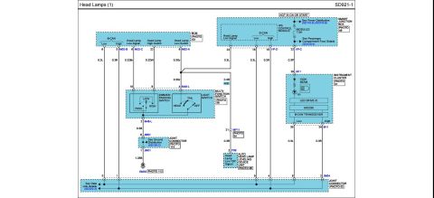








Electrical wiring diagram for the headlamp circuit showing multifunction switch, junction box and instrument cluster connections.
Part of 2010-2016 Hyundai Genesis Coupe Wiring Diagrams
This document is page SD921-1, "Head Lamps (1)," a factory-style wiring diagram covering the head lamp control circuits of a Hyundai Genesis Coupe (per uploader's filing; the page itself carries no explicit year/model). It shows the Smart Junction Box (Photo 49) with its IPS Control Module powered when hot in ON or START through the MODULE2 7.5A fuse, referencing Power Distribution pages SD110-8/SD110-9 and Passenger Compartment Fuse Details SD120-4. The BCM (Photo 63) communicates over B-CAN (Low/High) and provides Head Lamp Low Signal, High Switch, and Low Switch lines through connectors M02-A, M02-B, and M02-C with wire sizes/colors such as 0.3L, 0.3R, 0.22Br, 0.22W, and 0.3Gr. The Multi-Function Switch (Photo 56, connector M48-L) contains the dimmer/passing switch (PASS/LOW/HIGH) and light switch (HEAD/TAIL/OFF), grounding through joint connector JM01 (Photo 113) to ground point GM02 (Photo 112) via a 1.25B wire. An HID branch routes a Head Lamp Low 'ON' Signal through connectors MF11 and F06 to the Auto Head Lamp Leveling Device Unit (Photo 95). The Instrument Cluster (Photo 51, connector M11) includes the high beam indicator, LED drive IC, MICOM, and B-CAN transceiver, tying into data link joint connector JM04 (Photo 52, ref SD200-3).
Is this accurate? Sign in to help verify it.
Frequently asked questions
- What fuse powers the headlamp IPS control circuit in this diagram?
- The MODULE2 7.5A fuse in the Smart Junction Box, powered when hot in ON or START; see Power Distribution SD110-8/SD110-9 and Passenger Compartment Fuse Details SD120-4.
- Which connector does the multi-function (dimmer/light) switch use?
- Connector M48-L, with pins 10 and 9 for the dimmer/passing switch (0.22Br and 0.22W wires), pin 4 for the light switch (0.3Gr), and pin 2 to ground (0.3B).
- Where does the headlamp switch circuit ground?
- Through joint connector JM01 (pins 6 and 1, Photo 113) via a 1.25B wire to ground point GM02 (Photo 112), per Ground Distribution SD130-2.
- What controls the auto headlamp leveling on HID-equipped cars in this diagram?
- A Head Lamp Low 'ON' Signal (0.3R wire) runs through pin 21 of connector MF11 to pin 2 of connector F06 into the Auto Head Lamp Leveling Device Unit (Photo 95).
- What components in the instrument cluster relate to the headlamps here?
- The high beam indicator on connector M11 pin 29 (0.3P wire), plus an LED drive IC, MICOM, and B-CAN transceiver with B-CAN Low/High on pins 35 and 34.

No comments yet.