Home/
Registry/
Ford/
Bronco/
1987-1991/
“Eddie Bauer”/
Photo
supermotors.net/registry/media/1046658
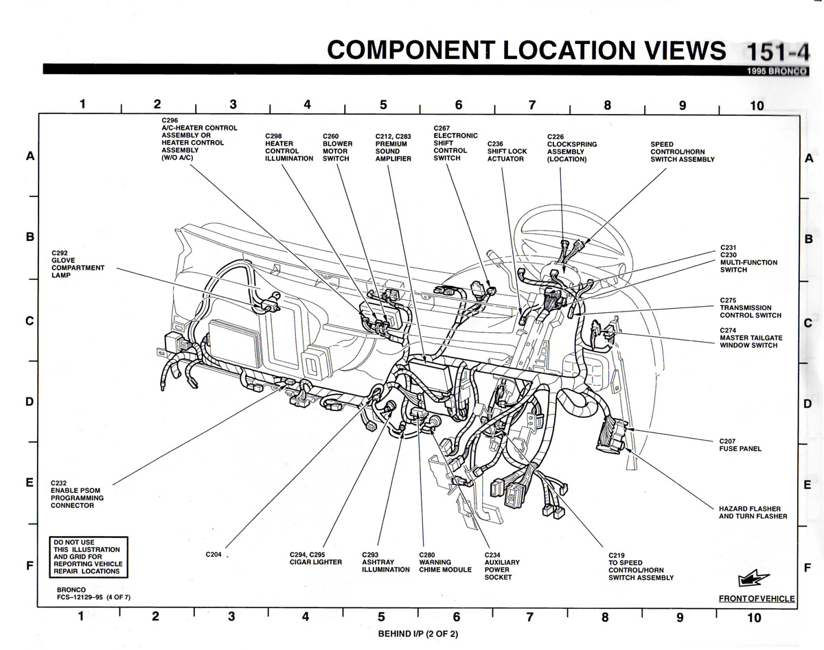
1995 Ford Bronco Component Location Views 151-4 - Behind Instrument Panel
Reference · 1987-1991 BroncoAll 53 manual pages
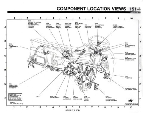








Service manual component location view showing connectors and wiring harness routing behind the instrument panel.
Part of 1987-1991 Ford Bronco Manual Pages
This is page 151-4 of the 1995 Ford Bronco Electrical and Vacuum Troubleshooting Manual (EVTM), titled "Component Location Views." It presents a detailed line-art illustration of the area behind the instrument panel (labeled "BEHIND I/P (2 OF 2)"), showing the dash wiring harness and the physical locations of numerous electrical connectors and components. Callouts identify connectors including C296 (A/C-heater or heater control assembly), C298 (heater control illumination), C260 (blower motor switch), C212/C283 (premium sound amplifier), C267 (electronic shift control switch), C236 (shift lock actuator), C226 (clockspring assembly location), C292 (glove compartment lamp), C230/C231 (multi-function switch), C275 (transmission control switch), C274 (master tailgate window switch), C232 (Enable PSOM programming connector), C204, C294/C295 (cigar lighter), C293 (ashtray illumination), C280 (warning chime module), C234 (auxiliary power socket), C219 (to speed control/horn switch assembly), C207 (fuse panel), and the hazard/turn flashers. A grid (columns 1-10, rows A-F) aids location referencing, though a boxed note warns not to use the grid for reporting vehicle repair locations. Document reference: FCS-12129-95 (4 of 7).
Is this accurate? Sign in to help verify it.
Frequently asked questions
- Where is the fuse panel connector shown on the 1995 Bronco dash diagram?
- The fuse panel is identified as C207, located on the driver's side behind the instrument panel near the hazard flasher and turn flasher.
- What connectors are listed for the cigar lighter and auxiliary power socket?
- The cigar lighter uses connectors C294 and C295, and the auxiliary power socket uses connector C234.
- Where is the warning chime module located in a 1995 Bronco?
- The warning chime module (connector C280) is shown behind the instrument panel, near the center of the dash between the ashtray illumination (C293) and auxiliary power socket (C234).
- What connector is the multi-function switch on the 1995 Bronco?
- The multi-function switch uses connectors C230 and C231, located near the steering column.
- What is the PSOM programming connector on this diagram?
- C232 is labeled the Enable PSOM Programming Connector, shown on the left side behind the instrument panel.






No comments yet.