Home/
Registry/
Ford/
Bronco/
1987-1991/
“Eddie Bauer”/
Photo
supermotors.net/registry/media/1046657
1995 Ford Bronco Warning Chime Module C280 Connector Pinout & Wire Colors (66-2)
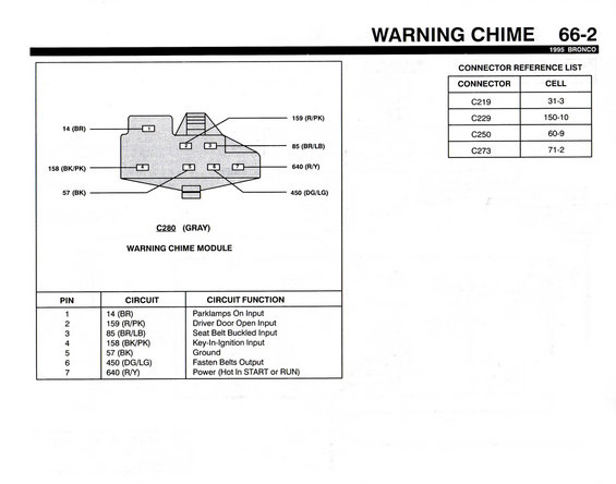
Wiring diagram of warning chime module connector C280 with pin-by-pin circuit functions and wire color codes.
This document is page 66-2 of the 1995 Ford Bronco electrical/wiring manual covering the Warning Chime system. It shows the connector face diagram for connector C280 (gray), which plugs into the Warning Chime Module, with all seven pins labeled by circuit number and wire color. A pinout table details each pin's circuit and function: pin 1 is circuit 14 (Brown) for the Parklamps On Input; pin 2 is circuit 159 (Red/Pink) for the Driver Door Open Input; pin 3 is circuit 85 (Brown/Light Blue) for the Seat Belt Buckled Input; pin 4 is circuit 158 (Black/Pink) for the Key-In-Ignition Input; pin 5 is circuit 57 (Black) Ground; pin 6 is circuit 450 (Dark Green/Light Green) for the Fasten Belts Output; and pin 7 is circuit 640 (Red/Yellow) for Power (Hot in START or RUN). A Connector Reference List cross-references related connectors C219 (cell 31-3), C229 (cell 150-10), C250 (cell 60-9), and C273 (cell 71-2). This page is useful for diagnosing warning chime problems such as chimes that stay on, don't sound, or seat belt/key-in-ignition reminder faults, by identifying wire colors and pin functions at the chime module connector.
Is this accurate? Sign in to help verify it.
Frequently asked questions
- What connector plugs into the warning chime module on a 1995 Bronco?
- Connector C280, a gray 7-pin connector, connects to the Warning Chime Module.
- Which wire provides power to the 1995 Bronco warning chime module?
- Pin 7, circuit 640 (Red/Yellow), is the power feed, hot in START or RUN.
- What wire color is the seat belt buckled input at the chime module?
- Pin 3, circuit 85, a Brown/Light Blue (BR/LB) wire, is the Seat Belt Buckled Input.
- Which pin is ground on the warning chime module connector?
- Pin 5, circuit 57, a Black (BK) wire, is the ground.
- What circuit signals the chime module that the key is in the ignition?
- Pin 4, circuit 158 (Black/Pink, BK/PK), is the Key-In-Ignition Input.
Comments
More from this build














No comments yet.