Home/
Registry/
Hyundai/
Genesis Coupe/
2010-2016/
“Coupe”/
Photo
supermotors.net/registry/media/1054106
Hyundai Genesis Coupe 2.0L G4KF MFI Control System Wiring Diagram SD313-4
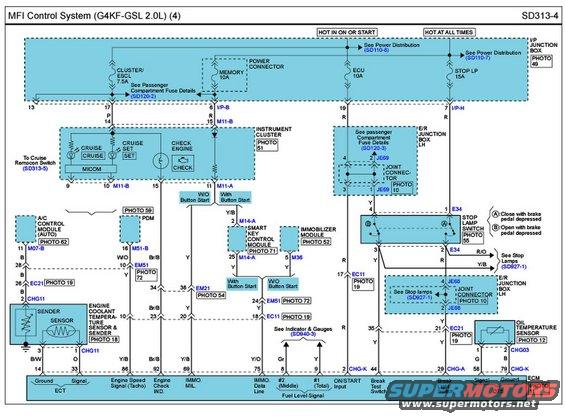
Electrical wiring diagram of the MFI control system showing instrument cluster, button-start, immobilizer and stop-lamp switch circuits.
Part of 2010-2016 Hyundai Genesis Coupe Wiring Diagrams
This is page 4 of the MFI (Multiport Fuel Injection) Control System wiring diagram, sheet SD313-4, for the Hyundai G4KF-GSL 2.0L engine. It shows power distribution from the I/P Junction Box fuses, CLUSTER/ESCL 7.5A and MEMORY 10A (hot in ON or START), plus ECU 10A and STOP LP 15A (hot at all times), to the instrument cluster (CRUISE, SET, and CHECK ENGINE indicators via MICOM), the A/C control module (auto), PDM, smart key control module (with button start) vs. immobilizer module (without button start), stop lamp switch, engine coolant temperature sensor & sender, oil temperature sensor, and the ECM. ECM pin assignments are labeled along the bottom, including pin 14/33 (ECT ground/signal), 86 (engine speed/tacho signal), 92 (engine check indicator), 69 (IMMO MIL), 75 (IMMO data line), 8/9 (fuel level signals), 2 (ON/START input), 44 (break test switch), 29 (break light switch), and 58/79 (OTS signal/ground). Wire colors (Y/B, Br/B, B/W, O, Gr, R/O, W/O, etc.), connector IDs (M11-A/B, M14-A, EC11, EC21, EM21, EM51, E34, JE68/JE69, CHG-series), photo references, and cross-references to related diagrams (SD110-7/8, SD120-2/3, SD313-5, SD927-1, SD940-3) are included. Stop lamp switch operation notes indicate contact A closes and contact B opens with brake pedal depressed.
Is this accurate? Sign in to help verify it.
Frequently asked questions
- What fuses power the MFI control system circuits shown on SD313-4?
- The I/P junction box supplies CLUSTER/ESCL 7.5A and MEMORY 10A (hot in ON or START), plus ECU 10A and STOP LP 15A (hot at all times).
- Which ECM pins carry the fuel level signals?
- ECM pin 8 (Gr wire) carries the #2 (Middle) fuel level signal and pin 9 (Y wire) carries the #1 (Total) fuel level signal.
- What ECM pin is the engine speed (tacho) signal on?
- Pin 86, with a Y/B wire, labeled Engine Speed Signal (Tacho).
- How does the stop lamp switch operate according to this diagram?
- Contact (A) closes with the brake pedal depressed and contact (B) opens with the brake pedal depressed. Its outputs route via connector E34 with R/O and Y/B wires to the stop lamps (see SD927-1).
- Which module is used with push-button start versus without?
- With button start, the circuit goes to the Smart Key Control Module (connector M14-A); without button start, it goes to the Immobilizer Module (connector M36).
Comments
More from this build









No comments yet.