Home/
Registry/
Hyundai/
Genesis Coupe/
2010-2016/
“Coupe”/
Photo
supermotors.net/registry/media/1054114
Hyundai Genesis Coupe 2.0L G4KF Power Distribution Wiring Diagram SD110-4
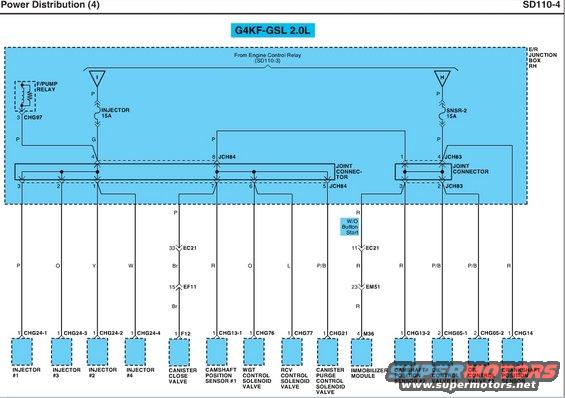
Power distribution wiring diagram for a Hyundai G4KF 2.0L engine covering injectors, camshaft sensor, solenoid valves, and immobilizer module.
Part of 2010-2016 Hyundai Genesis Coupe Wiring Diagrams
This document is page SD110-4, "Power Distribution (4)," a wiring diagram for the G4KF-GSL 2.0L engine. It shows power flow from the Engine Control Relay (referenced on SD110-3) through the E/R (engine room) Junction Box RH. Two fused branches are shown: the INJECTOR 15A fuse (branch I) and the SNSR-2 15A fuse (branch H). Power passes through joint connectors JCH84 and JCH83 and is distributed to engine management components. The INJECTOR 15A circuit feeds Injectors #1-#4 (via connectors CHG24-1 through CHG24-4, wire colors P, O, Y, W) and the fuel pump relay (F/PUMP RELAY, CHG97). The SNSR-2 15A circuit feeds the canister close valve (F12, via EC21 and EF11), camshaft position sensors #1 and #2 (CHG13-1, CHG13-2), WGT control solenoid valve (CHG76), RCV control solenoid valve (CHG77), canister purge control solenoid valve (CHG21), immobilizer module (M36, without button start, via EC21/EM51), oil control valves #1 and #2 (CHG05-1, CHG05-2), and the crankshaft position sensor (CHG14). Wire colors (P, G, O, Y, W, Br, R, L, P/B) and connector pin numbers are labeled throughout, useful for tracing power supply circuits for these components.
Is this accurate? Sign in to help verify it.
Frequently asked questions
- What fuses supply the injectors and sensors on the G4KF 2.0L engine?
- The INJECTOR 15A fuse (branch I) and the SNSR-2 15A fuse (branch H), both fed from the Engine Control Relay (SD110-3) in the E/R Junction Box RH.
- What wire colors go to each injector?
- Injector #1: P (pin 1, CHG24-1); Injector #3: O (CHG24-3); Injector #2: Y (CHG24-2); Injector #4: W (CHG24-4).
- Which components receive power from the SNSR-2 15A fuse?
- Via joint connector JCH83: camshaft position sensors #1 and #2, WGT control solenoid valve, RCV control solenoid valve, canister purge control solenoid valve, canister close valve, immobilizer module (W/O button start), oil control valves #1 and #2, and the crankshaft position sensor.
- What connector feeds the crankshaft position sensor and what wire color is used?
- The crankshaft position sensor is fed on a red (R) wire at pin 1 of connector CHG14.
- How does the immobilizer module get power?
- On vehicles without button start, an R wire runs from joint connector JCH83 through connector EC21 (pin 11) and EM51 (pin 23) to pin 4 of connector M36 at the immobilizer module.
Comments
More from this build









No comments yet.