Home/
Registry/
Hyundai/
Genesis Coupe/
2010-2016/
“Coupe”/
Photo
supermotors.net/registry/media/1054116
Hyundai Genesis Coupe 3.8L Power Distribution Wiring Diagram SD110-6 G6DA-GSL
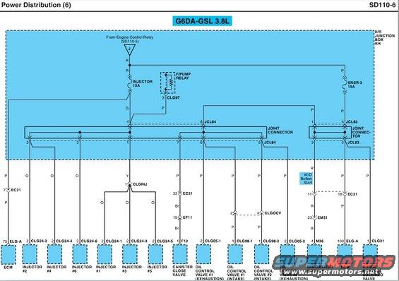
Power distribution wiring diagram for a Hyundai G6DA 3.8L engine covering injectors, fuel pump relay, canister valves, and oil control valves.
Part of 2010-2016 Hyundai Genesis Coupe Wiring Diagrams
This is page SD110-6, "Power Distribution (6)," a factory wiring diagram for the G6DA-GSL 3.8L engine (Hyundai Genesis Coupe). It shows how battery/ignition power from the Engine Control Relay (referenced on sheet SD110-5) is distributed inside the E/R (engine room) Junction Box RH through two fuses: the 15A INJECTOR fuse and the 15A SNSR-2 fuse, plus the Fuel Pump (F/PUMP) Relay via connector CLG97. Power flows through joint connectors JCL84 and JCL83, then fans out to individual components with wire colors and connector pin numbers: ECM (pins 75 and 100 of ELG-A), all six fuel injectors (connectors CLG24-1 through CLG24-6 via joint connector CLGINJ), the canister close valve (connector F12 via EC21 pin 33 and EF11 pin 15), four oil control valves for intake and exhaust cams (CLG05-1, CLG05-2, CLG98-1, CLG98-2, via CLGOCV), the immobilizer module (M36 pin 4, applicable without button start, via EM51 pin 23), and the purge control solenoid valve (CLG21 pin 1). Wire colors shown include R (red), P (pink), O (orange), G (green), Y (yellow), and Br (brown). A reader can trace fuse-to-component power circuits and identify connector pinouts for diagnostics.
Is this accurate? Sign in to help verify it.
Frequently asked questions
- What fuses supply power in this Genesis Coupe 3.8L power distribution diagram?
- Two 15A fuses in the E/R Junction Box RH: the INJECTOR 15A fuse and the SNSR-2 15A fuse, both fed from the Engine Control Relay (referenced on sheet SD110-5).
- Which fuse powers the fuel injectors on the 3.8L G6DA engine?
- The INJECTOR 15A fuse feeds joint connector JCL84, which distributes power on orange wires to injectors #1-#6 through connectors CLG24-1 through CLG24-6 (injectors 1, 3, and 5 pass through joint connector CLGINJ pin 1 on a yellow wire).
- What components does the SNSR-2 15A fuse power?
- Through joint connector JCL83, the SNSR-2 fuse supplies the immobilizer module (M36 pin 4, without button start, via EM51 pin 23), the ECM (ELG-A pin 100 via EC21 pin 18), and the purge control solenoid valve (CLG21 pin 1).
- How is the canister close valve powered?
- Power runs from JCL84 pin 7 on a pink (P) wire to EC21 pin 33, then on brown (Br) wire through EF11 pin 15 to connector F12 pin 1 at the canister close valve.
- Which connectors serve the oil control valves?
- CLG05-1 (oil control valve #1 exhaust), CLG98-1 (valve #1 intake), CLG98-2 (valve #2 intake), and CLG05-2 (valve #2 exhaust), with intake valves fed through joint connector CLGOCV, all on pink (P) wires from JCL84.
Comments
More from this build









No comments yet.