Home/
Registry/
Hyundai/
Genesis Coupe/
2010-2016/
“Coupe”/
Photo
supermotors.net/registry/media/1054119
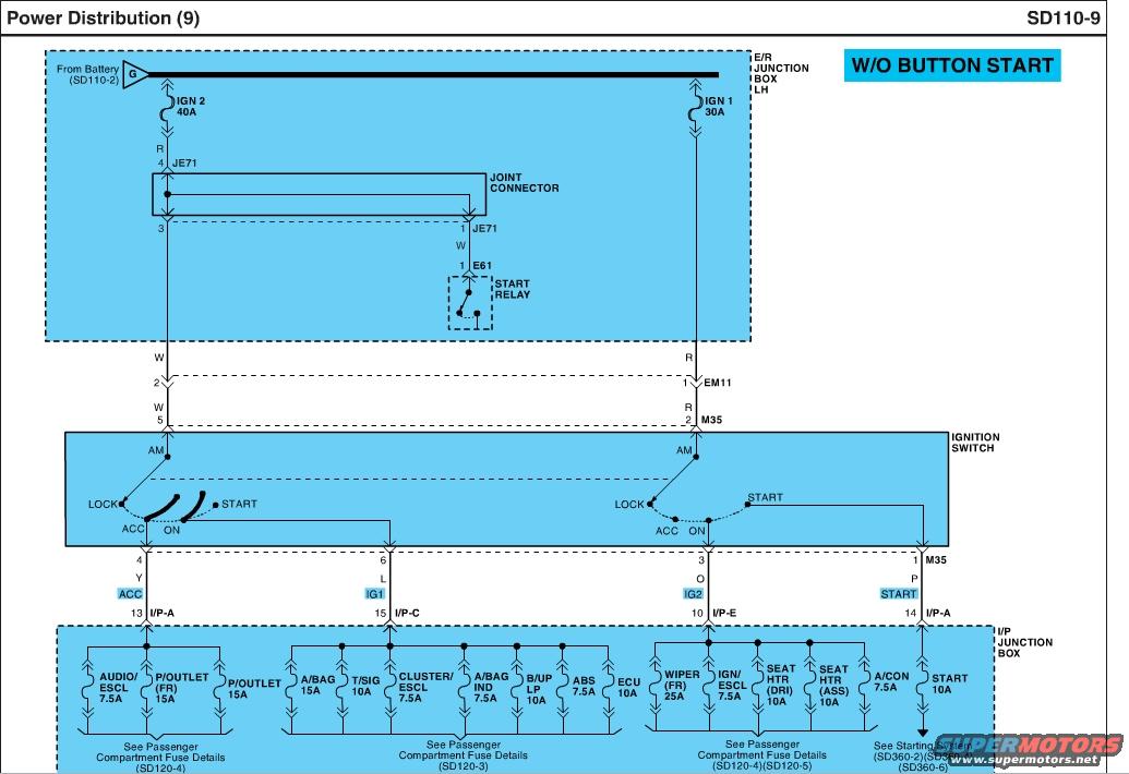
Hyundai Genesis Coupe Power Distribution Wiring Diagram SD110-9 (W/O Button Start)
Reference · 2010-2016 Genesis CoupeAll 79 wiring diagrams
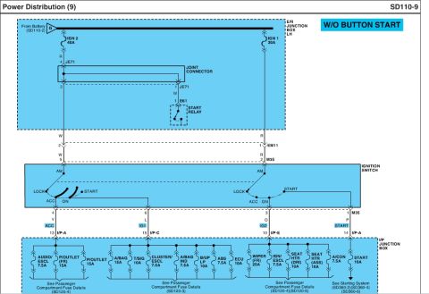
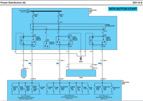
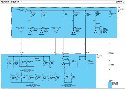
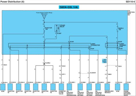
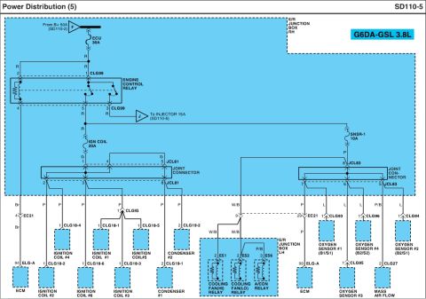








Power distribution schematic (page SD110-9, W/O button start) tracing E/R junction box IGN1/IGN2 through the ignition switch to passenger-compartment fuses for audio, cluster, ABS, HVAC and ECU.
Part of 2010-2016 Hyundai Genesis Coupe Wiring Diagrams
This is page SD110-9, "Power Distribution (9)," a wiring diagram for vehicles without button (push-button) start. It traces ignition-switched power from the battery through the E/R (engine room) junction box LH, where the IGN 2 40A and IGN 1 30A fuses feed the ignition switch via joint connector JE71, connectors EM11 and M35, and the start relay (connector E61). The ignition switch (positions LOCK, ACC, ON, START) distributes power on four outputs: ACC (wire Y, pin 4 M35 to I/P-A pin 13), IG1 (wire L, pin 6 to I/P-C pin 15), IG2 (wire O, pin 3 to I/P-E pin 10), and START (wire P, pin 1 to I/P-A pin 14). Inside the I/P junction box, the ACC circuit feeds AUDIO/ESCL 7.5A, P/OUTLET (FR) 15A, and P/OUTLET 15A fuses; IG1 feeds A/BAG 15A, T/SIG 10A, CLUSTER/ESCL 7.5A, A/BAG IND 7.5A, B/UP LP 10A, ABS 7.5A, and ECU 10A; IG2 feeds WIPER (FR) 25A, IGN/ESCL 7.5A, SEAT HTR (DRI) 10A, SEAT HTR (ASS) 10A, and A/CON 7.5A; START feeds a START 10A fuse to the starting system. Cross-references are given to fuse detail pages SD120-3/4/5 and starting system pages SD360-2/4/6.
Is this accurate? Sign in to help verify it.
Frequently asked questions
- What fuses feed the ignition switch power in this diagram?
- IGN 2 (40A) and IGN 1 (30A), both located in the E/R Junction Box LH and fed from the battery (see SD110-2).
- Which fuses are on the ACC circuit?
- AUDIO/ESCL 7.5A, P/OUTLET (FR) 15A, and P/OUTLET 15A, fed through I/P-A pin 13 in the I/P junction box (details on SD120-4).
- What fuses does the IG1 circuit supply?
- A/BAG 15A, T/SIG 10A, CLUSTER/ESCL 7.5A, A/BAG IND 7.5A, B/UP LP 10A, ABS 7.5A, and ECU 10A (details on SD120-3).
- What is on the IG2 circuit?
- WIPER (FR) 25A, IGN/ESCL 7.5A, SEAT HTR (DRI) 10A, SEAT HTR (ASS) 10A, and A/CON 7.5A, fed via I/P-E pin 10 (see SD120-4 and SD120-5).
- Does this diagram apply to push-button start cars?
- No, it is labeled 'W/O BUTTON START,' meaning it applies to vehicles without push-button start.

No comments yet.