Home/
Registry/
Hyundai/
Genesis Coupe/
2010-2016/
“Coupe”/
Photo
supermotors.net/registry/media/1058129
Hyundai Genesis Coupe A/C Control System Wiring Diagram (Manual) SD971-7

Reference · 2010-2016 Genesis CoupeAll 79 wiring diagrams
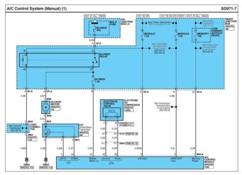
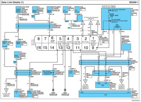
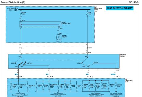
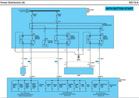
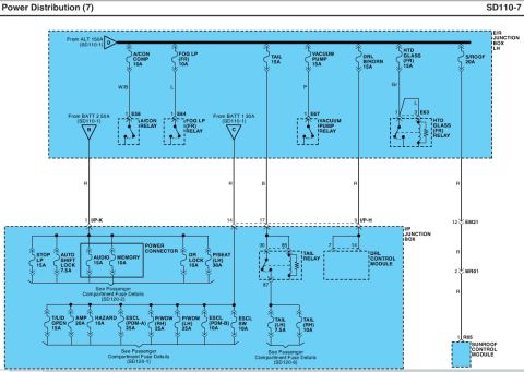








Manual A/C control system wiring diagram showing blower relay, blower motor, electronic control valve, and electronic A/C compressor circuits.
Part of 2010-2016 Hyundai Genesis Coupe Wiring Diagrams
This is page SD971-7 of a Hyundai factory wiring diagram titled 'A/C Control System (Manual) (1)'. It shows the manual air conditioning control circuit, including power feeds labeled HOT AT ALL TIMES, HOT IN ON, and HOT IN ON OR START. Power comes from the E/R Junction Box LH through a 40A BLOWER multi fuse and from the Smart Junction Box, which contains the blower relay, a 7.5A BLOWER fuse, 7.5A MODULE7 and MODULE2 fuses, and a 10A MEMORY1 fuse with leak current autocut device. The diagram traces circuits to the blower motor (connector M08), the FET field effect transistor (connector M24) with GATE and DRAIN lines, the electrical control valve of the electronic A/C compressor (with CHG28/G4KF and CLG28/G6DJ engine-variant connectors via EC21 and EM51), and the A/C Control Module (connector M06-A) with pins for blower motor (+), ECV ground and power, ON input, ON/START input, and memory power. Wire gauges and colors (e.g., 3.0W, 3.0P, 3.0G, 0.3B, 0.3R, 0.3Br, 1.25B) are labeled, along with grounds GM02 and GM04 and cross-references to power distribution (SD110-7/8/9), passenger compartment fuse details (SD120-2/4/5), and ground distribution (SD130-2).
Is this accurate? Sign in to help verify it.
Frequently asked questions
- What fuses protect the manual A/C blower circuit in this diagram?
- A 40A BLOWER multi fuse in the E/R Junction Box LH feeds the blower relay, and a 7.5A BLOWER fuse in the Smart Junction Box protects the relay control side. MODULE7 (7.5A), MODULE2 (7.5A), and MEMORY1 (10A) fuses also supply the A/C control module.
- Where is the blower relay located?
- The blower relay (pins 30, 85, 86, 87) is inside the Smart Junction Box, shown with reference PHOTO 49.
- What controls blower motor speed in this circuit?
- A FET (Field Effect Transistor), connector M24, shown with PHOTO 69. Its GATE (0.3W wire, pin 5) and DRAIN (0.3Y wire, pin 16) connect to the A/C Control Module connector M06-A.
- Which A/C Control Module pins carry power and ground for the electronic compressor control valve?
- Pin 34 is Power (0.3R wire) and pin 35 is Ground (0.3B wire) for the ECV, routed through connectors EC21 and EM51, with engine-specific connectors CHG28 (G4KF) and CLG28 (G6DJ).
- What ground points are used in this A/C circuit?
- GM02 (via joint connector JM01 with a 1.25B wire) and GM04 (via a 3.0B wire from the FET), shown with PHOTO 112 and PHOTO 114.

No comments yet.