Home/
Registry/
Hyundai/
Genesis Coupe/
2010-2016/
“Coupe”/
Photo
supermotors.net/registry/media/1064021
Hyundai Genesis Coupe Power Outside Mirror Wiring Diagram SD876-1
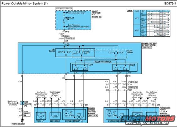
Power outside mirror wiring diagram showing the mirror switch, selector switch, and driver and passenger mirror motor circuits with a function table.
Part of 2010-2016 Hyundai Genesis Coupe Wiring Diagrams
This document is page SD876-1, "Power Outside Mirror System (1)," a factory-style wiring diagram for power-adjustable outside mirrors. Power comes from the Smart Junction Box (see Power Distribution SD110-8/SD110-9) through the 7.5A MODULE1 fuse, hot in ACC or ON, feeding the ACC+ terminal (pin 1 of connector D03) at the power outside mirror switch (PHOTO 77). The switch contains up/down and left/right adjustment contacts plus a LEFT/RIGHT selector switch. Outputs VL, HL, VR, and HR route through connectors D03, FD11, and FD21 to the driver-side mirror (connector D04, PHOTO 76) and passenger-side mirror (connector D14, PHOTO 79). Each mirror assembly contains up/down and left/right positioning motors plus a turn lamp and defogger element (referenced to SD925-2 Turn & Hazard Lamps and SD879-1 Defogger System). Wire gauges and colors are labeled (0.3W, 0.3G, 0.3L, 0.3Y, 0.3O, 0.3Gr, 0.3B, 0.3R/O, 1.25B), with ground at GF01 via joint UDA (Ground Distribution SD120-6). A switch-logic table in the upper right shows which terminals connect for each mirror selection (LEFT/RIGHT) and movement direction (UP, DOWN, OFF, LEFT, RIGHT). Useful for diagnosing inoperative mirror adjustment, checking fuse and switch continuity, and tracing wiring between switch and mirrors.
Is this accurate? Sign in to help verify it.
Frequently asked questions
- What fuse powers the power outside mirror system?
- The MODULE1 7.5A fuse in the Smart Junction Box, hot in ACC or ON (see Power Distribution SD110-8/SD110-9 and Passenger Compartment Fuse Details SD120-1).
- Which connector serves the power outside mirror switch?
- Connector D03: pin 1 is ACC+, pin 8 is E (ground side), pin 6 is C, pin 4 is VL, pin 5 is HL, pin 3 is VR, and pin 2 is HR.
- What components are inside each mirror assembly?
- Each mirror (LH via connector D04, RH via connector D14) contains an up/down motor, a right/left motor, a turn lamp, and a defogger element.
- Where does the mirror system ground?
- Through joint UDA and a 1.25B wire via pin 39 of connector FD11 to ground point GF01 (see Ground Distribution SD120-6).
- What connectors route wiring to the passenger-side mirror?
- Signals pass through connector FD21 (pins 26, 8, 7 with 0.3L, 0.3O, 0.3Gr wires) to the passenger mirror connector D14.
Comments
More from this build









No comments yet.