Home/
Registry/
Hyundai/
Genesis Coupe/
2010-2016/
“Coupe”/
Photo
supermotors.net/registry/media/1064020
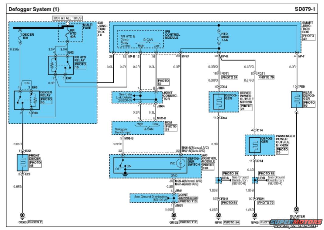
Hyundai Genesis Coupe Defogger System Wiring Diagram SD879-1 - Rear & Mirror
Reference · 2010-2016 Genesis CoupeAll 79 wiring diagrams
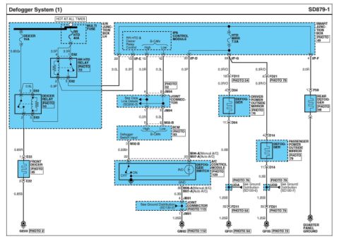
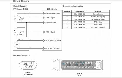
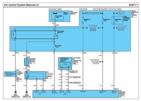
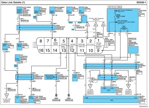








Rear defogger system wiring diagram showing the HTD relay, control module, front and rear deicers, and heated outside mirror circuits.
Part of 2010-2016 Hyundai Genesis Coupe Wiring Diagrams
This document is page SD879-1, "Defogger System (1)," a factory-style wiring diagram covering the rear defogger, front deicer, and heated outside mirror circuits. Power originates from the E/R Junction Box LH via a multi fuse feeding the DEICER 15A and RR HTD 40A fuses (hot at all times), which supply the Deicer Relay (E63) and RR HTD Relay (E62). The Smart Junction Box houses the IPS Control Module (which controls the RR HTD & Deicer relays and communicates over B-CAN High/Low lines) and the HTD MIRR 7.5A fuse. B-CAN wiring routes through joint connector JM04 to the BCM (connector M02-B), which receives the defogger switch input. The Defogger Switch with indicator lamp is part of the A/C Control Module (connectors M06-A for Manual A/C, M07-A for Auto A/C). Outputs feed the front deicer (E22), driver power outside mirror defogger (D04 via FD11), passenger power outside mirror defogger (D14 via FD21), and the rear defogger (F59), grounding at GE03, GM02, GF01, GF05, and the quarter panel ground. Wire gauges and colors (e.g., 0.85Gr, 3.0P, 3.0R, 0.3R/O, 0.3B, 1.25B) and connector pin numbers are labeled throughout, with cross-references to ground distribution diagrams SD130-2/6/7 and data link details SD200-3.
Is this accurate? Sign in to help verify it.
Frequently asked questions
- What fuses power the defogger system in this diagram?
- Three fuses are shown: DEICER 15A and RR HTD 40A in the E/R Junction Box LH (both hot at all times), and HTD MIRR 7.5A in the Smart Junction Box for the heated outside mirrors.
- What relays control the rear defogger and deicer?
- The RR HTD Relay (connector E62) and the Deicer Relay (connector E63), both located in the E/R Junction Box LH and controlled by the IPS Control Module in the Smart Junction Box.
- What connector is the defogger switch on?
- The defogger switch is part of the A/C Control Module, using connector M06-A on Manual A/C vehicles or M07-A on Auto A/C vehicles, with signal on pins 22/23 and ground on pin 39.
- How are the heated outside mirrors wired?
- The HTD MIRR 7.5A fuse feeds 0.3R/O wires through Smart Junction Box connector I/P-G pin 28 to the driver mirror defogger (connector D04 via FD11) and passenger mirror defogger (connector D14 via FD21), grounding at GF01 and GF05 through UDA/UDB per ground distribution SD130-6 and SD130-7.
- Where does the rear defogger ground?
- The rear defogger (connector F59, fed by a 3.0R wire from the HTD MIRR circuit via I/P-F pin 4) grounds at the quarter panel ground.

No comments yet.