Home/
Registry/
Ford/
Bronco/
1987-1991/
“Eddie Bauer”/
Photo
supermotors.net/registry/media/1068885
Ford Bronco Speed Density Air Intake Tube & Air Cleaner Exploded Diagram

Reference · 1987-1991 BroncoAll 61 exploded parts diagrams

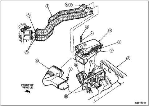











Exploded parts diagram of the air intake duct and air cleaner assembly with numbered and lettered callouts and a front-of-vehicle reference.
Part of 1987-1991 Ford Bronco Exploded Parts Diagrams
This is a scanned exploded-view parts diagram of a Ford air intake (air cleaner and air tube) system, filed by the uploader as "Air Tube SD" (speed density) for a 1990 Ford Bronco. The illustration shows the large corrugated air intake tube (callout 1) running from the throttle body area (callouts C and D) to the air cleaner housing (callout 5), with a clamp/fitting at the tube's rear end (callouts A and 2). The air cleaner assembly is shown exploded, including its cover fasteners (callouts 3 and 4), the lower tray/bracket assembly (callout 8) with mounting fasteners (callouts 7 and B), and the fresh air intake duct/snorkel (callout 10) with its retaining screw (callout 9). The fender apron/body panel is indicated by callout 6, and a "FRONT OF VEHICLE" arrow shows orientation. The Ford illustration reference number A25123-A appears at the lower right. No parts legend, part numbers, torque specifications, or year/model applicability text is printed on this page, so the diagram serves purely as a visual reference for how the speed-density air intake components fit together and mount in the engine compartment.
Is this accurate? Sign in to help verify it.
Frequently asked questions
- What does this diagram show?
- An exploded view of the air intake system: the corrugated air intake tube (1), air cleaner housing (5), lower tray/bracket (8), fresh air intake duct (10), and their clamps, screws, and fasteners (2, 3, 4, 7, 9, A-D), oriented with a FRONT OF VEHICLE arrow.
- How is the air intake tube attached?
- The diagram shows the tube (1) connecting to the throttle body area at callouts C/D on the left and secured at the air cleaner end with a clamp/fitting marked A and 2.
- Does this page list part numbers or torque specs?
- No. Only numbered/lettered callouts and the Ford illustration reference A25123-A appear; there is no parts legend, part numbers, or torque values on this page.
- How is the air cleaner assembly mounted?
- The air cleaner housing (5) sits on a lower tray/bracket assembly (8) that mounts near the fender apron (6), secured with fasteners shown at callouts 3, 4, 7, and B.






No comments yet.