Headlight Relay Wiring Diagram - Dual Relay Harness Upgrade (Ford Bronco)
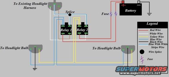
Headlight relay wiring diagram: two relays fed from the battery through fuses, tying into the existing headlight harness and bulbs, with a color legend for red/white/yellow/blue/black wires and splices.
This document is a color-coded wiring diagram for a headlight relay upgrade/conversion. It shows how two relays (Relay 1 and Relay 2) are wired between the vehicle's battery and the headlight bulbs, with the trigger signal taken from the existing headlight harness connector. Two fused red wires run from the battery positive terminal to the relays, while the battery negative terminal goes to ground. A splice point (shown as a filled black circle) joins wiring near the existing headlight harness connector. Blue and yellow wires run from the relays to the two headlight bulb connectors, each of which also has a black ground wire terminating at a ground symbol. A legend identifies the wire color codes used: red, white, yellow, blue, black, and blue with a white stripe, along with symbols for a wire splice, an in-line fuse, and ground. The diagram does not state a vehicle year, make, model, fuse amperage ratings, relay part numbers, or relay terminal numbers; it is a generic schematic-style illustration for adding relays to a headlight circuit so the headlights are powered directly from the battery rather than through the factory switch wiring.
Is this accurate? Sign in to help verify it.
Frequently asked questions
- How many relays does this headlight wiring upgrade use?
- The diagram shows two relays, labeled Relay 1 and Relay 2, wired between the battery and the headlight bulbs.
- Where does the power for the relays come from?
- Power comes from the battery positive terminal through two in-line fuses (red wires) to the relays; the battery negative terminal is grounded.
- What wire colors are used in this diagram?
- The legend lists red, white, yellow, blue, black, and blue with white stripe wires, plus symbols for a wire splice, fuse, and ground.
- How is the trigger signal for the relays obtained?
- The diagram shows a connection to the existing headlight harness, with a splice point joining wires that run to the relays.
- How are the headlight bulbs grounded?
- Each headlight bulb connector has a black wire running directly to a chassis ground, shown with a ground symbol.
Comments
More from this build






No comments yet.