Ford Alternator Voltage Regulator Test Diagram - Voltmeter Lead Placement

Reference · 1992-1996 BroncoAll 142 service procedures





Service illustration showing voltmeter positive and negative leads connected to the alternator voltage regulator A terminal screw.
Part of 1992-1996 Ford Bronco Service Procedures
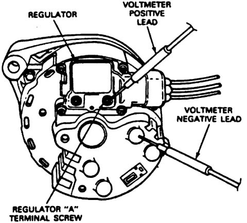
This document is a line-art illustration from a service manual showing how to test the voltage regulator on an alternator using a voltmeter. The drawing depicts the rear view of an alternator with its integral voltage regulator mounted on the back. Four callouts identify key items: the REGULATOR itself (mounted on the rear of the alternator housing), the REGULATOR "A" TERMINAL SCREW (indicated on the regulator assembly), and the placement of the two voltmeter test probes. The VOLTMETER POSITIVE LEAD is shown touching a point on the regulator/terminal area, while the VOLTMETER NEGATIVE LEAD is shown contacting the alternator case (ground). Wiring exits the alternator connector at the right side of the illustration. A reader can learn where to place voltmeter probes when checking regulator voltage at the "A" terminal screw relative to the alternator housing ground. The document contains no text beyond the four labels, no year, model, specification values, or part numbers are stated. It was uploaded to a 1995 Ford Bronco gallery alongside other engine and drivetrain service diagrams, and nothing in the image contradicts that attribution, though the diagram itself does not state applicability.
Is this accurate? Sign in to help verify it.
Frequently asked questions
- Where do I connect the voltmeter positive lead when testing the voltage regulator?
- Per the diagram, the voltmeter positive lead is placed at the regulator, in the area of the regulator "A" terminal screw on the back of the alternator.
- Where does the voltmeter negative lead go during this regulator test?
- The diagram shows the voltmeter negative lead touching the alternator case/housing (ground).
- Where is the voltage regulator located in this diagram?
- The regulator is shown mounted on the rear of the alternator, with the "A" terminal screw identified on the regulator assembly.
- Does this diagram give a voltage specification for the test?
- No. The illustration only labels the regulator, the "A" terminal screw, and the voltmeter positive and negative lead positions; no voltage values are shown.






No comments yet.